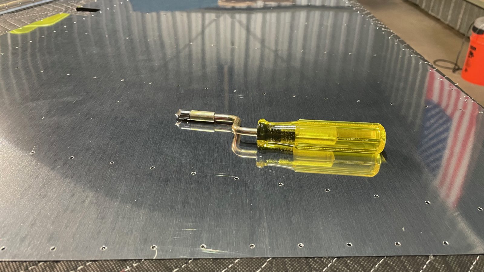
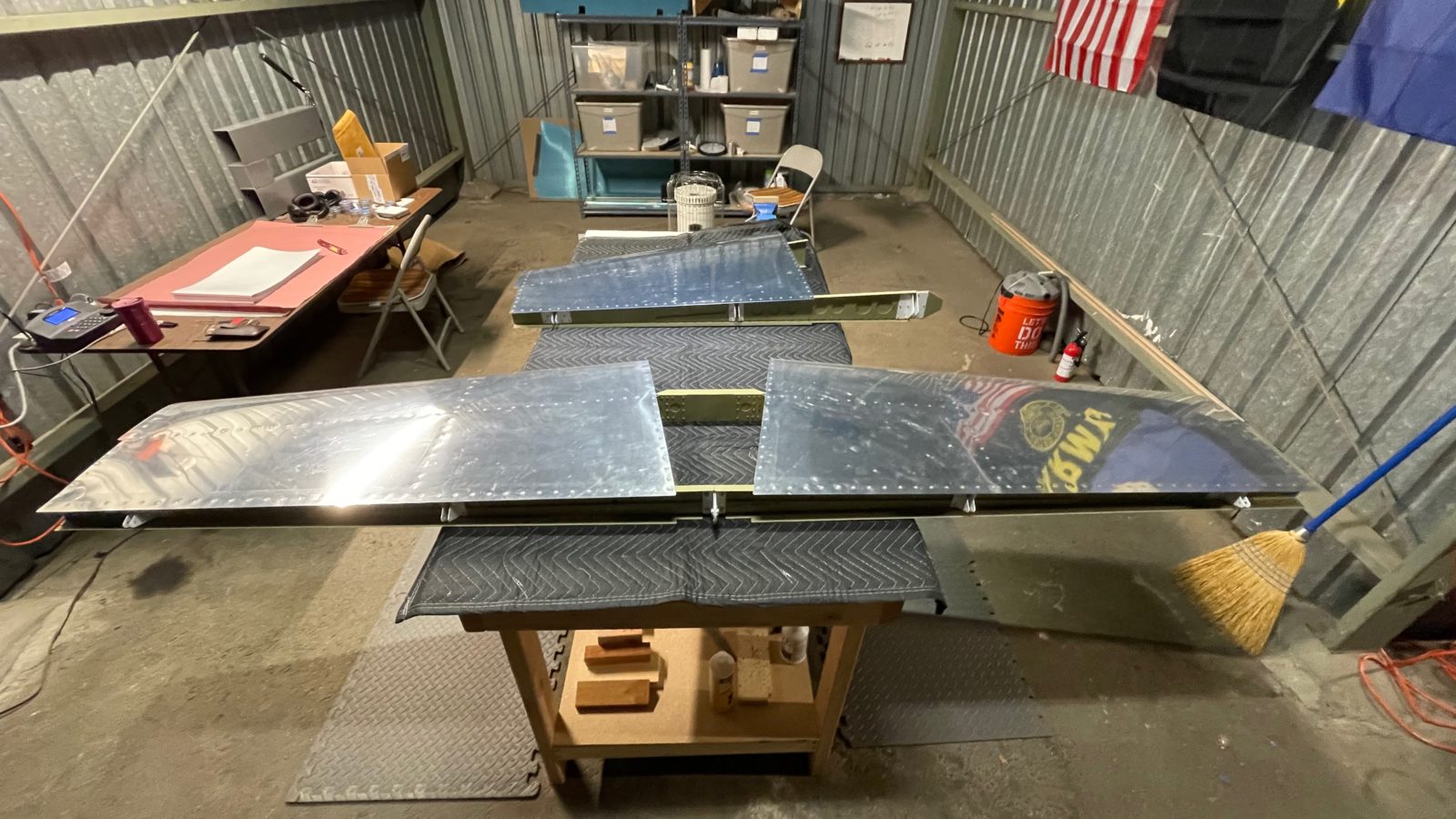
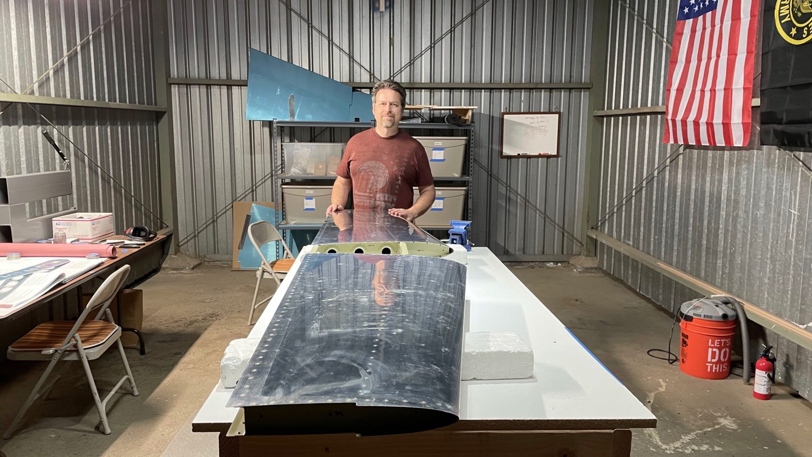
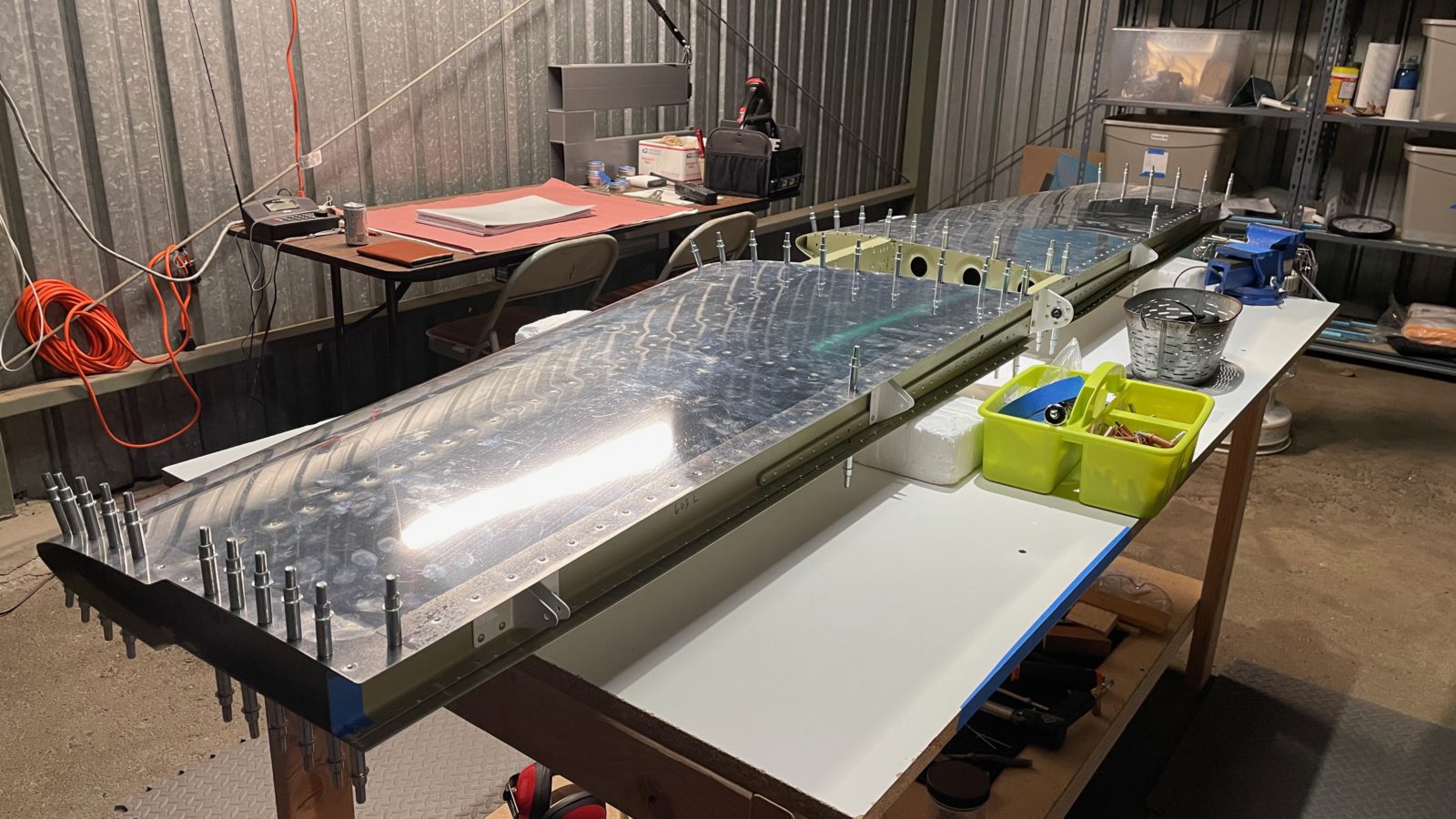
Was a gorgeous day today. Cooler than the previous couple days, which made it into the 80’s! Today the temperature leveled out around 70, and so we headed to the hangar to pick up work on the rudder. Today we cut and polished the remaining 8 stiffeners (left side). Sheila took care of dimpling all of them while I started working on deburring the skin. Earlier I had match-drilled the stiffeners and the skin.
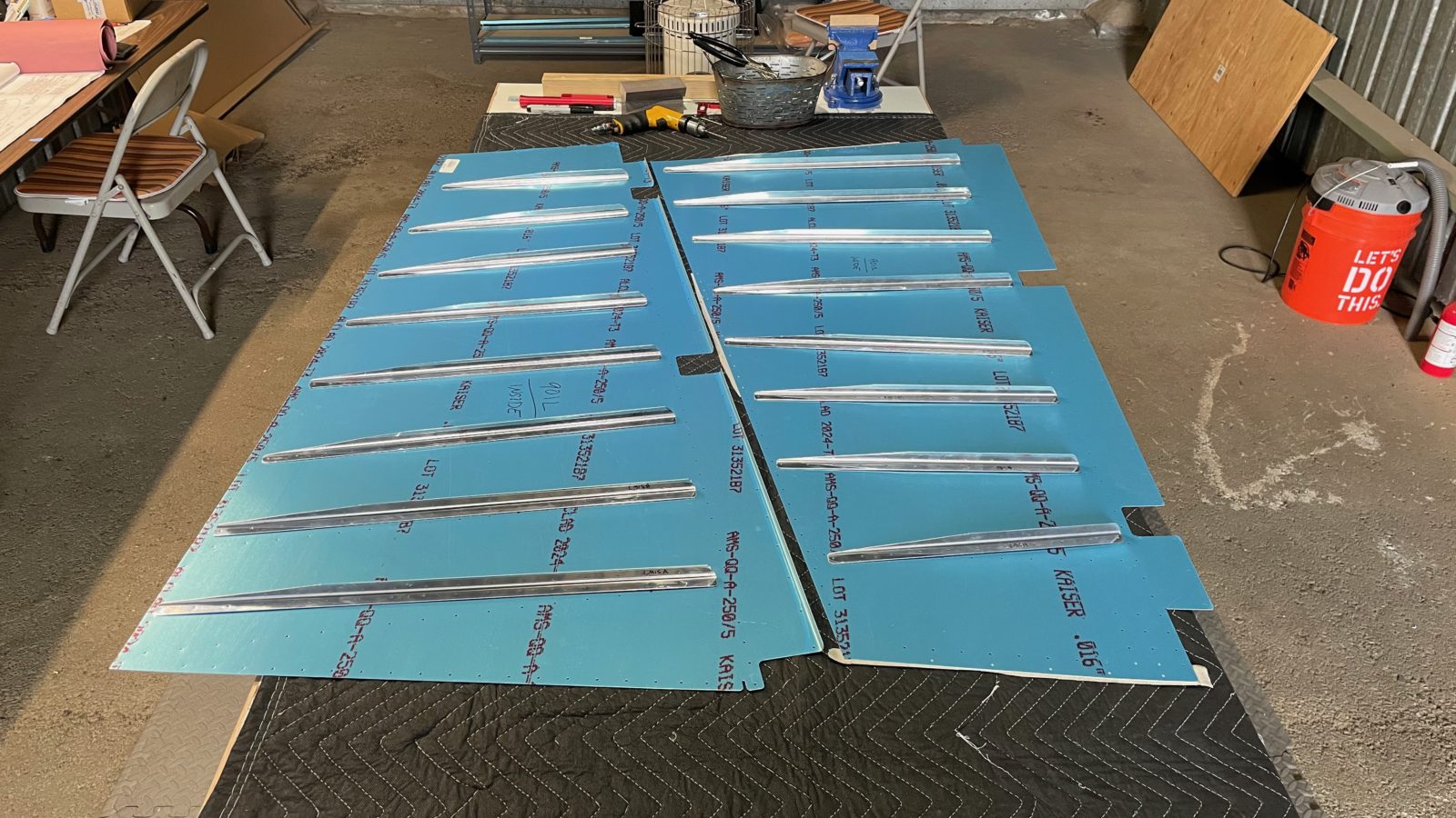
Today’s collection of photos.
Next up is finishing deburring the other skin, then CAREFULLY dimpling both skins. Afterwards, it’ll be time to load up everything, and the compressor, and head back the house for priming.
Today we started work on the rudder, which is the control surface responsible for motion about the yaw axis. It works primarily by deflecting air to the lef or right, and you use your rudder pedals in the cockpit to do so. According to the instructions, the rudder and the elevators will probably be the most challenging parts in the empennage assembly.
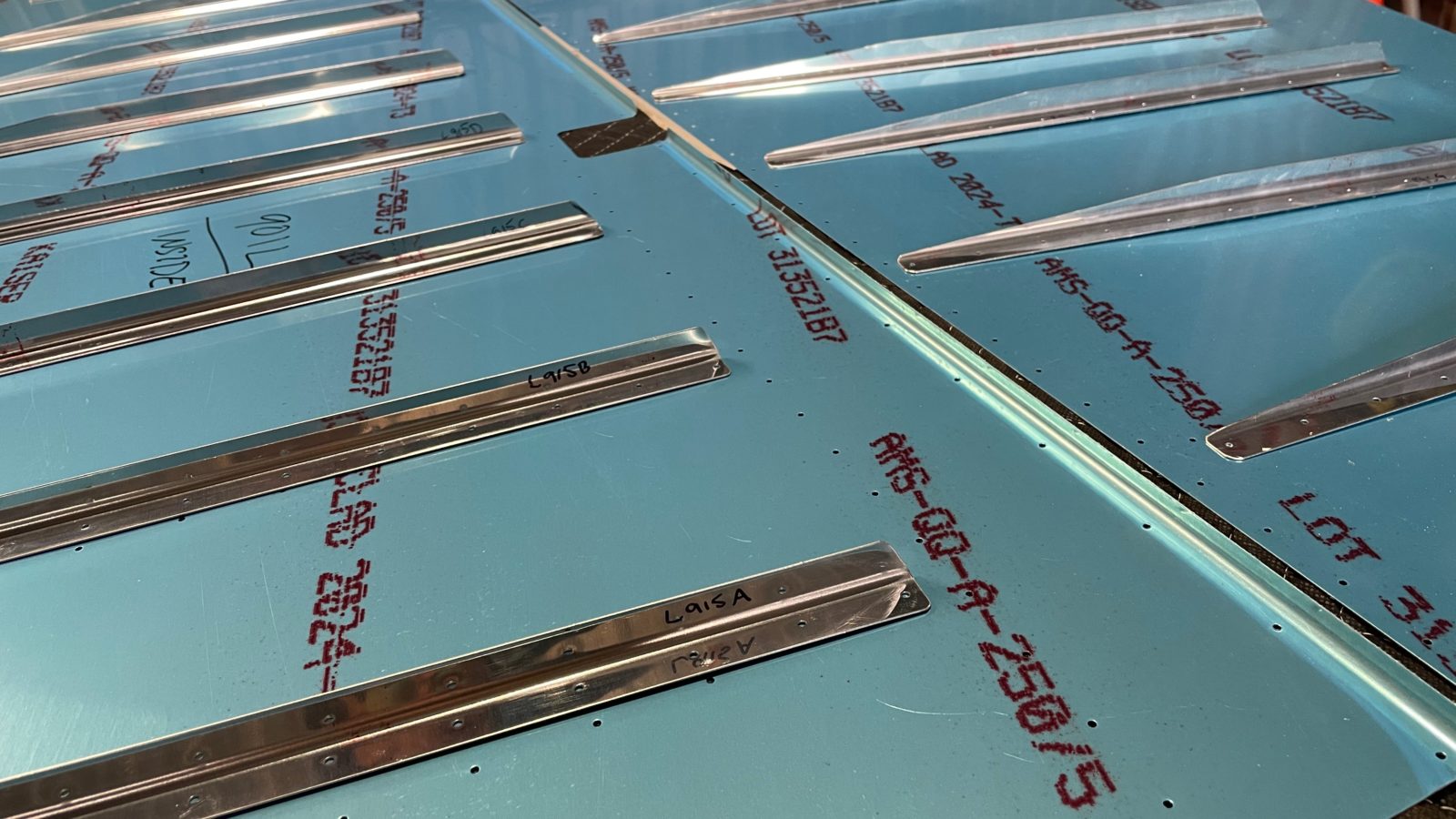
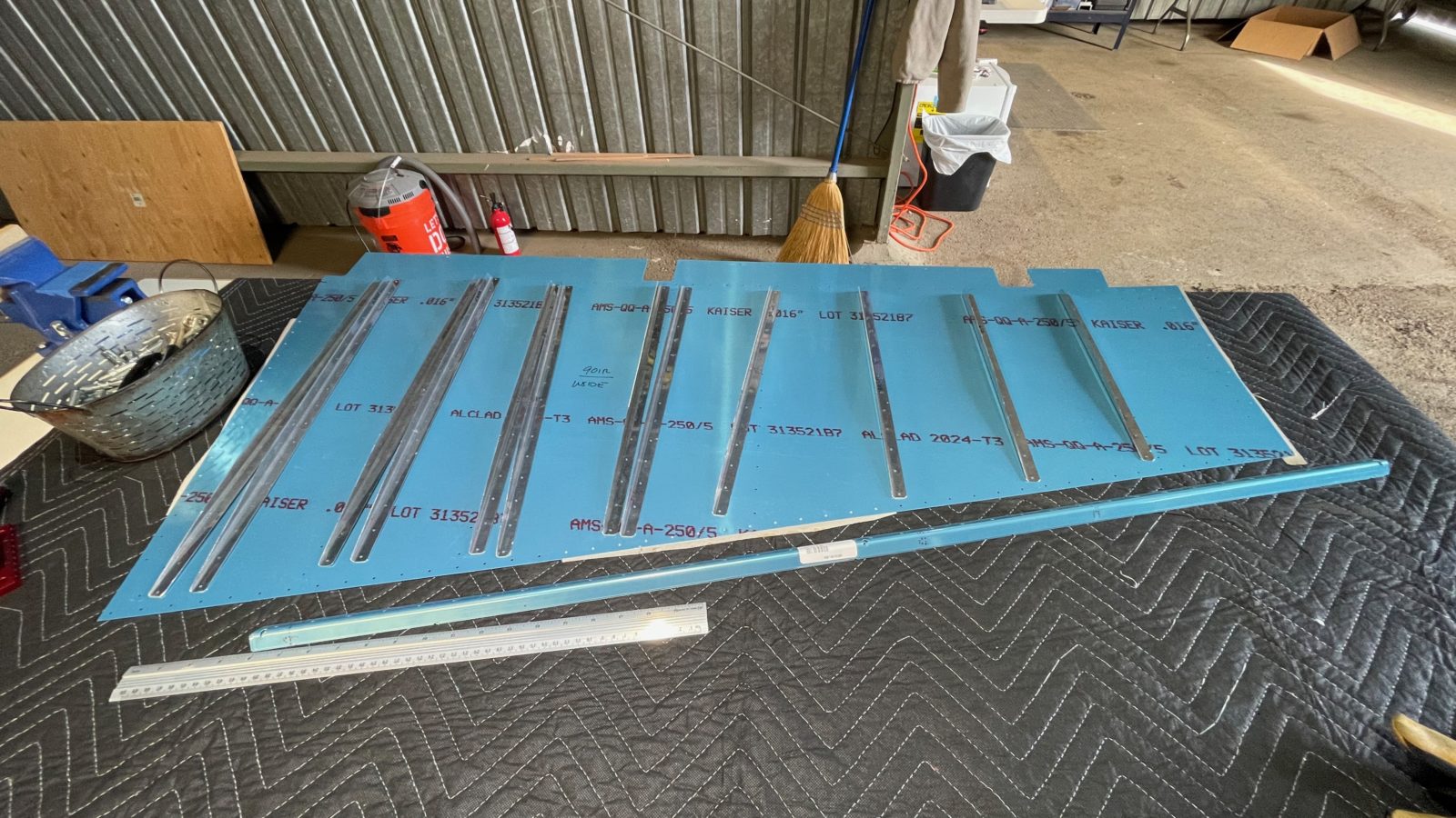
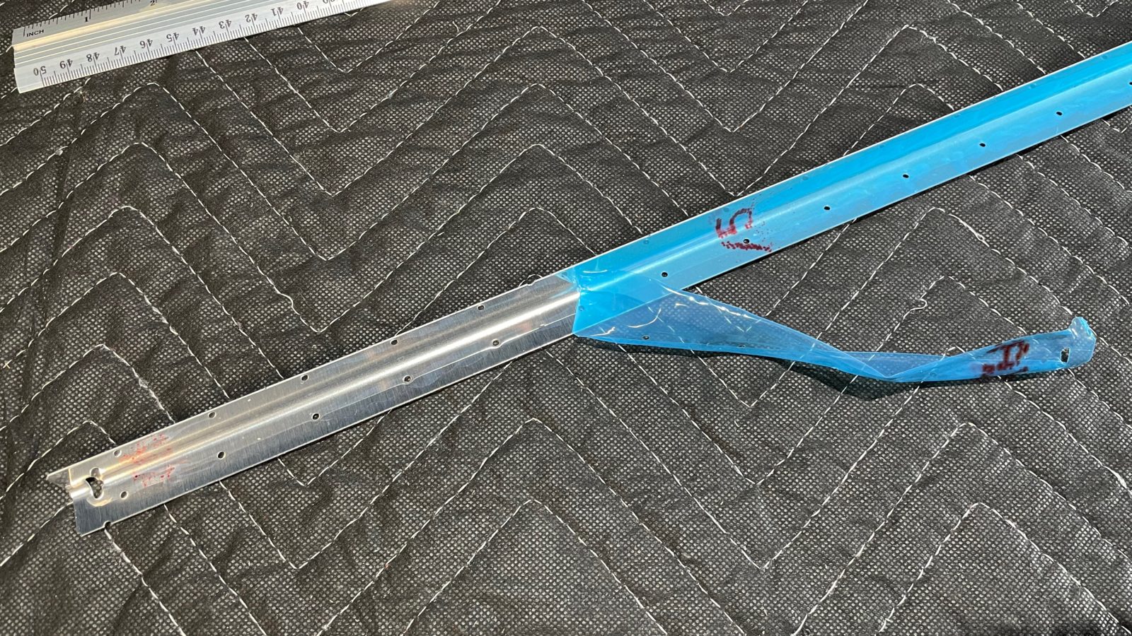
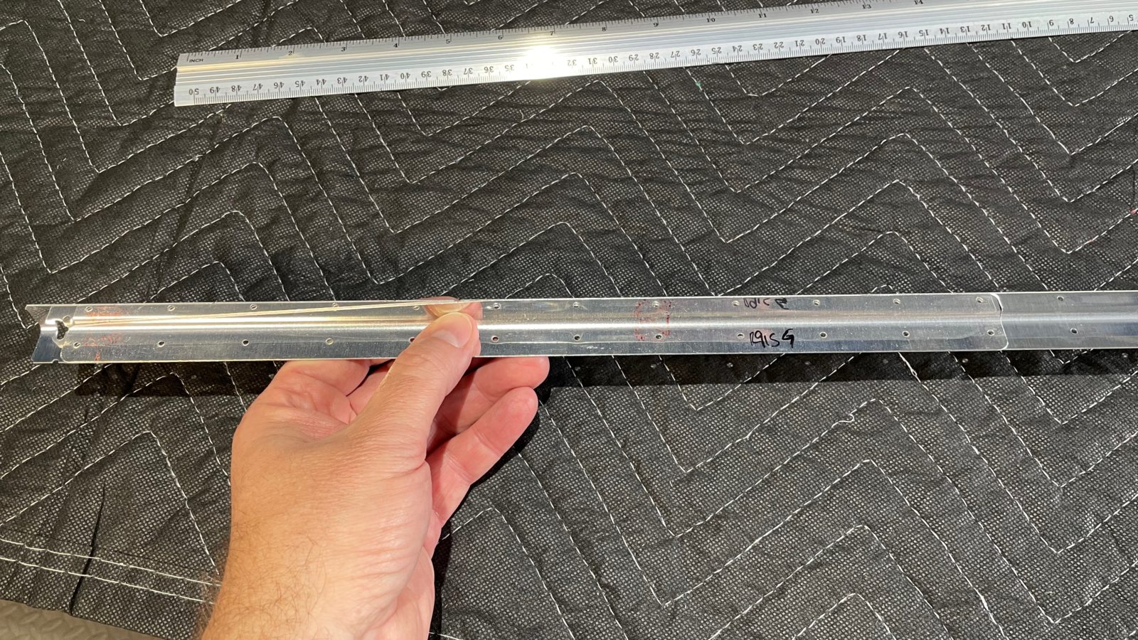
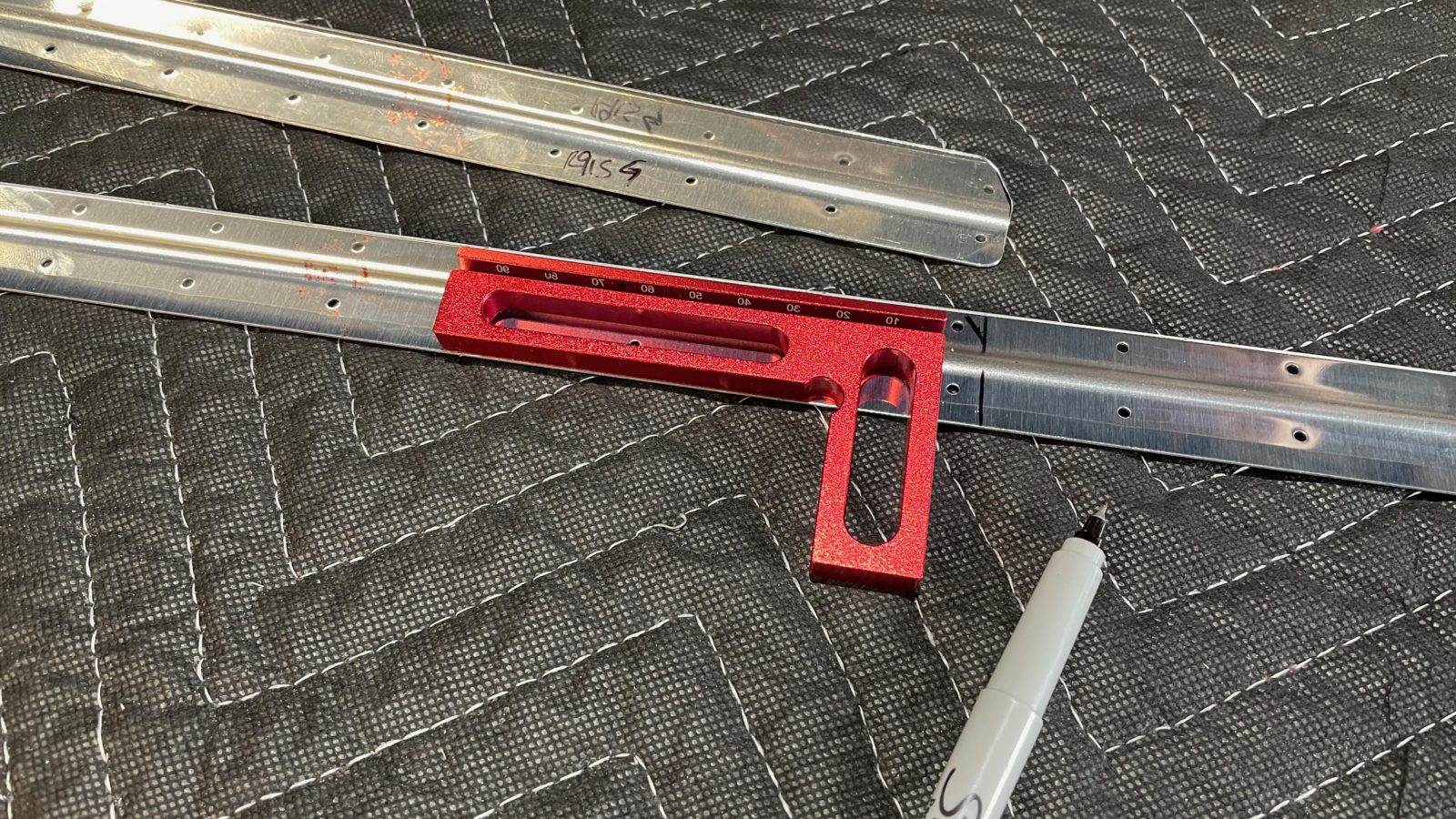
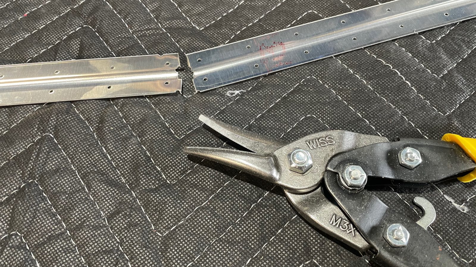
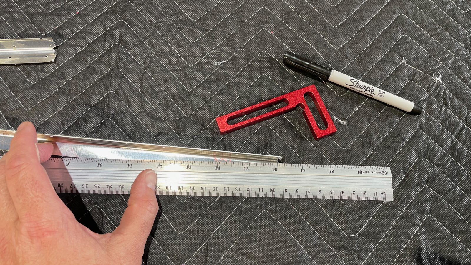
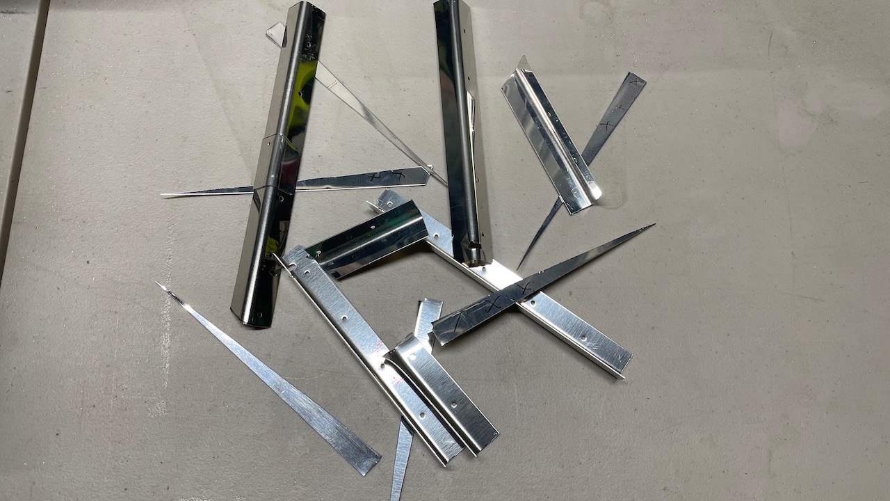
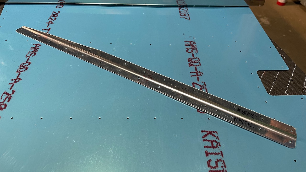
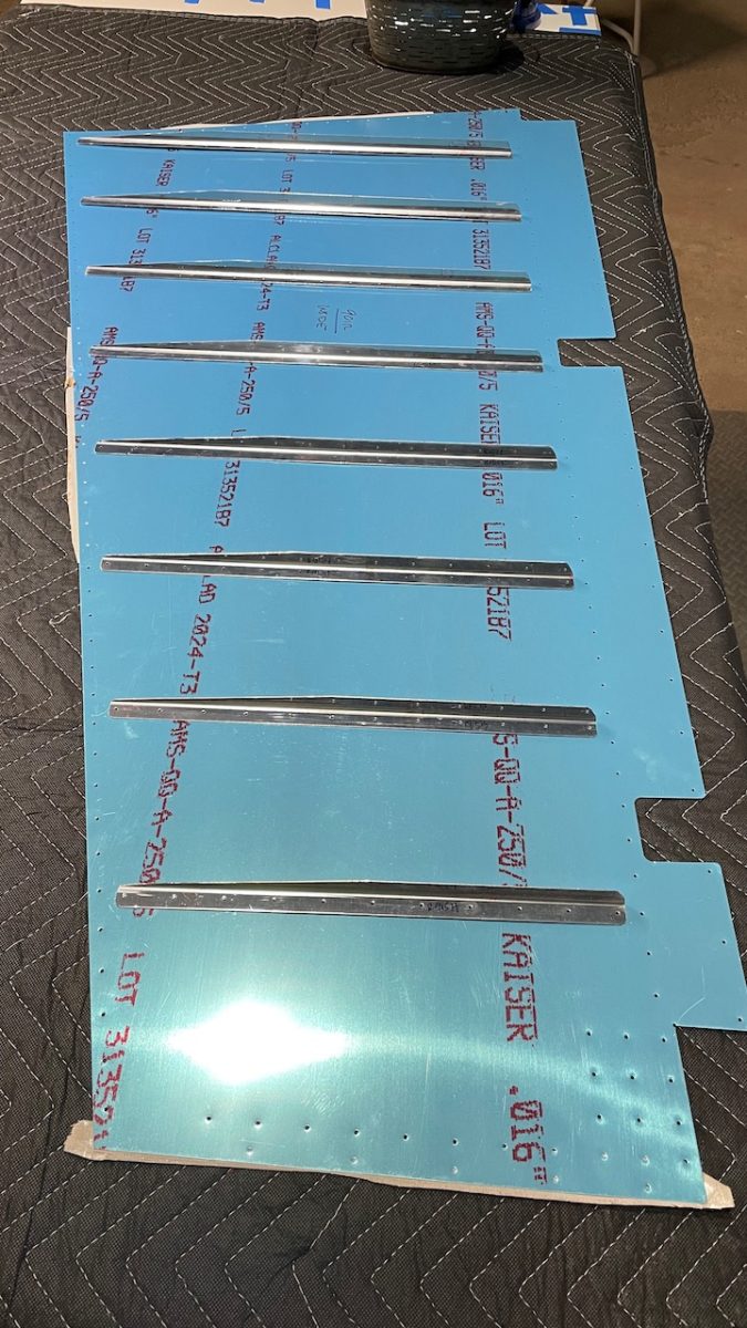
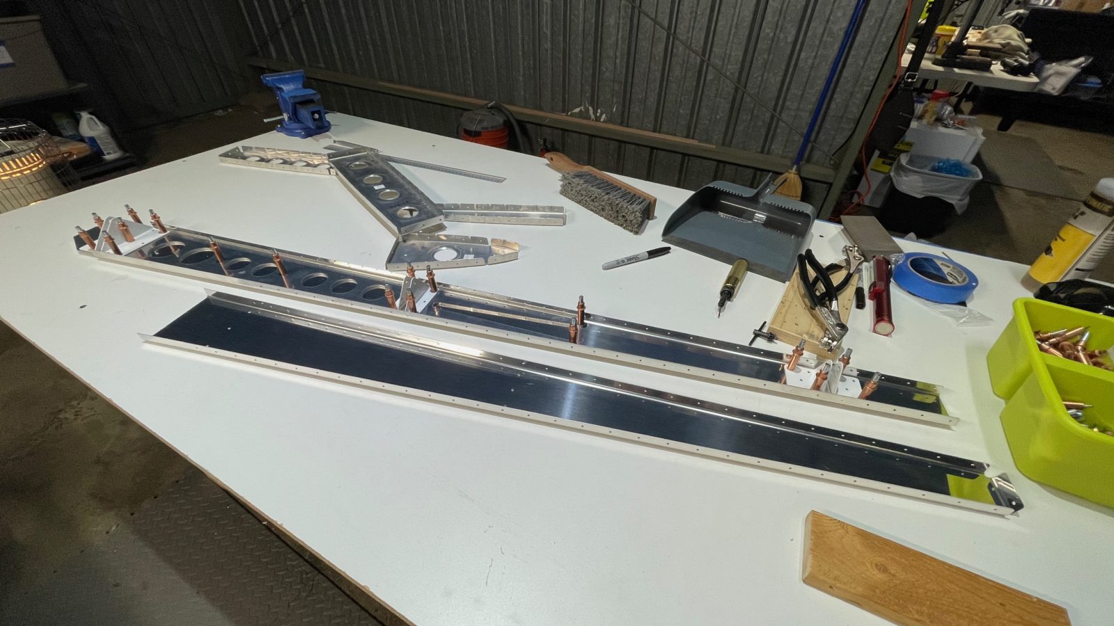
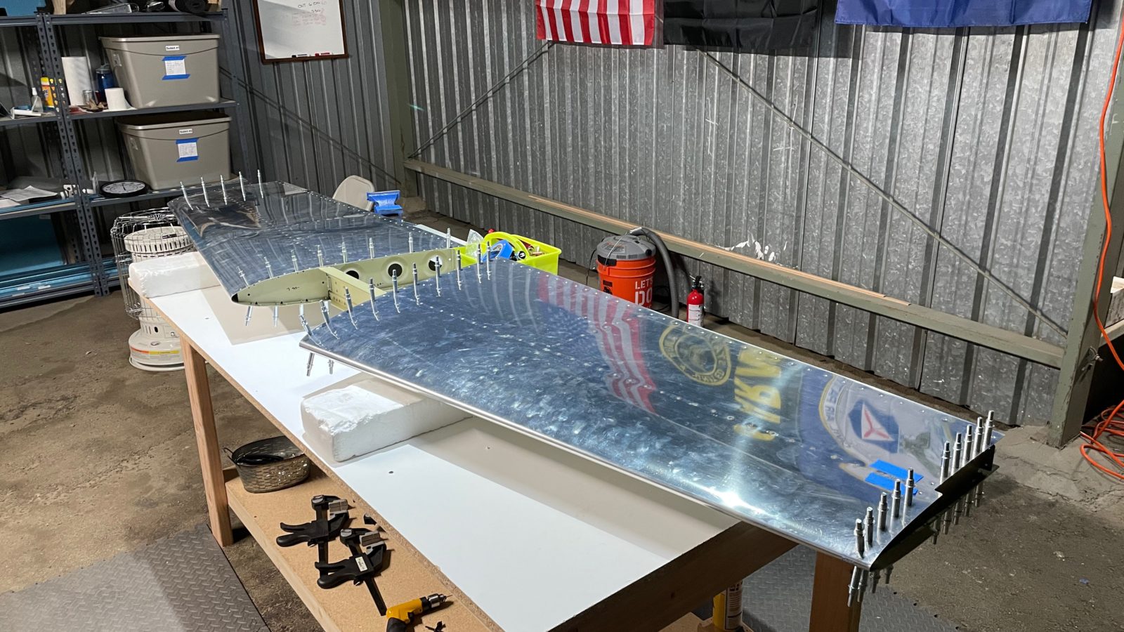
Tonight’s work started off with cutting apart some angle stock in order to form and shape stiffeners for the rudder. The rudder skin is about half the thickness of the stabilizer surfaces, so we have to be careful with them. The stiffeners increase their rigidity. Each stiffener stock part has to be cut in half, then shaped according to the plans. Fortunately, Van’s cut in small reference marks so we know where we have to cut the parts to the exact size.
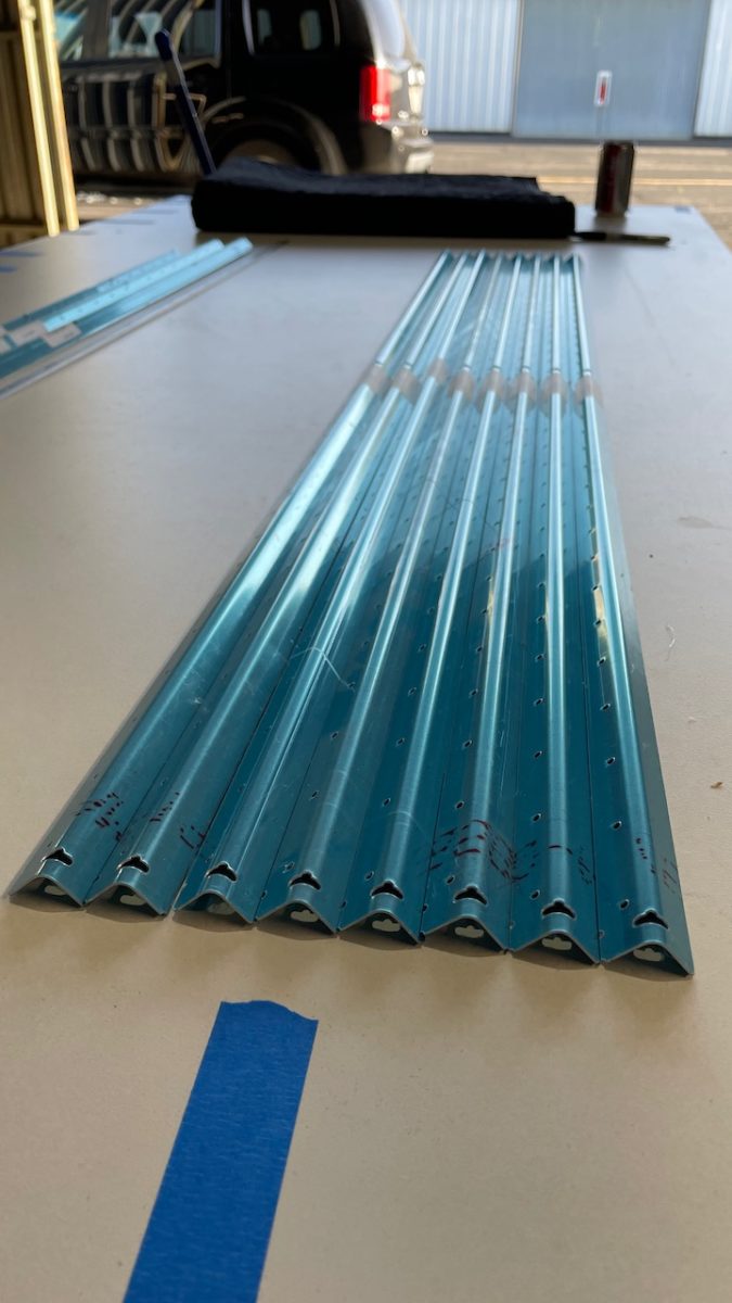
The stiffener stock piecesA finished stiffenerAll stiffeners for the right rudder skin
It didn’t take too much time to do the right side…about 2.5 hours total.We quite enjoy the challenge of fabricating the parts.
Next time we’ll cut down the stiffeners for the left skin. Then we move on to building the skeleton. The rudder and elevators have a heavy lead counterweight that helps with control forces while flying. They look pretty neat. You’ll see them in the next couple sessions.
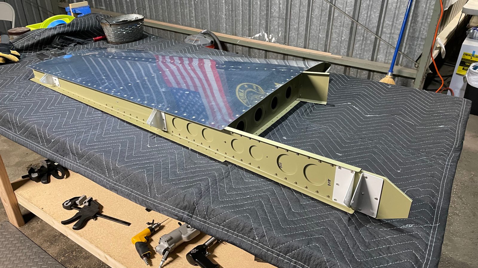
This weekend we had a marathon session (5.5 hours) to finish the vertical stabilizer! The work was quick now that we’re getting used to the workflow: fit, match drill, disassemble, deburr, dimple, prime, assemble. It also helped that this is a smaller component than the horizontal stabilizer.
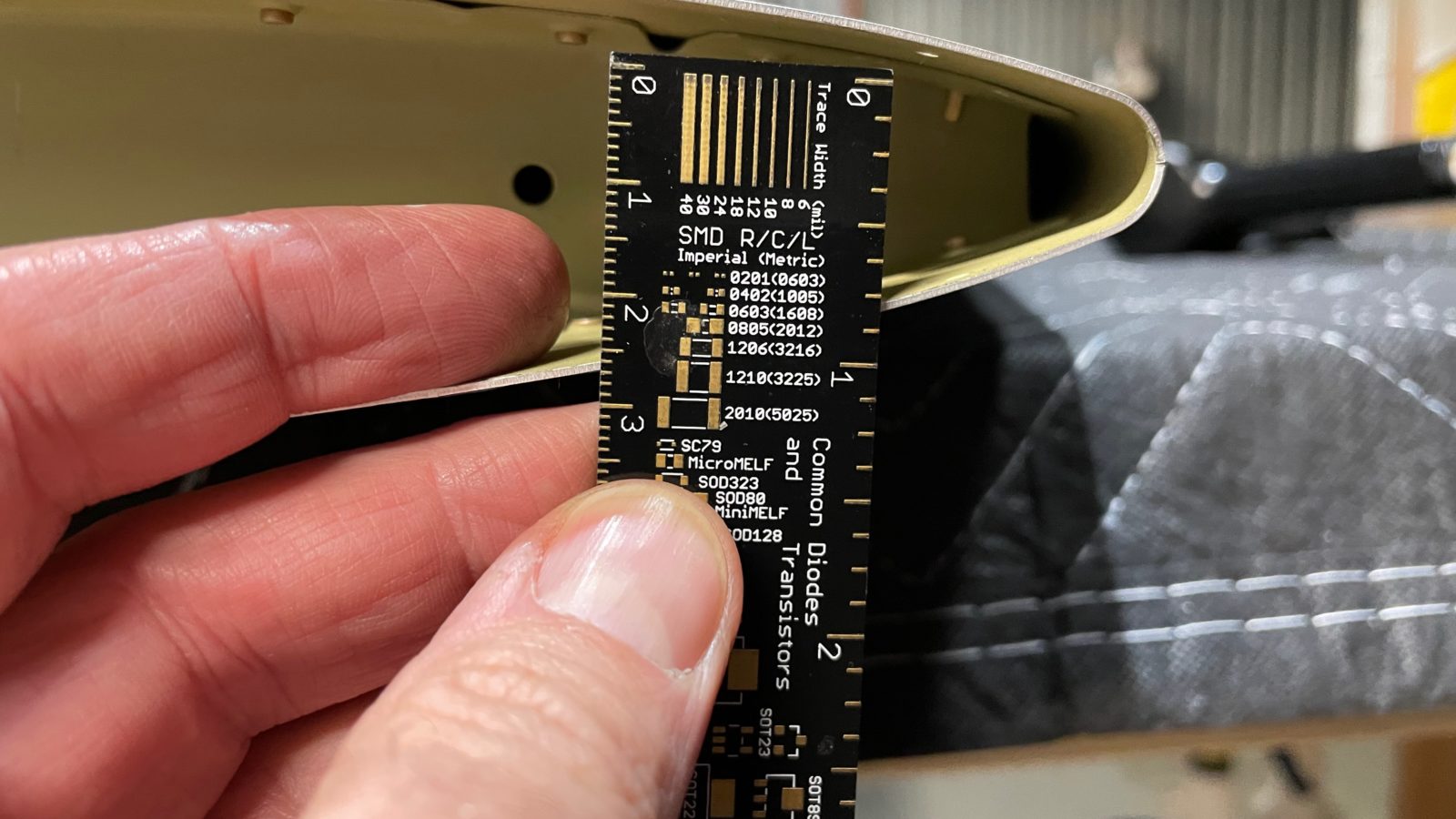
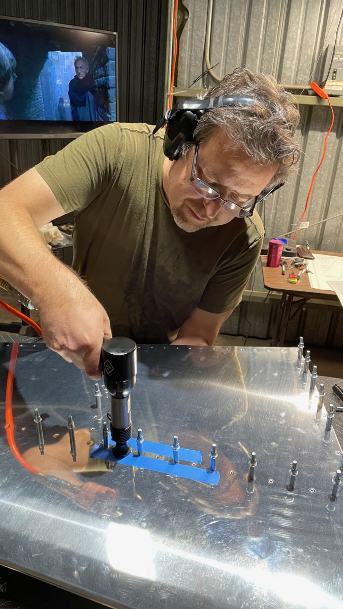
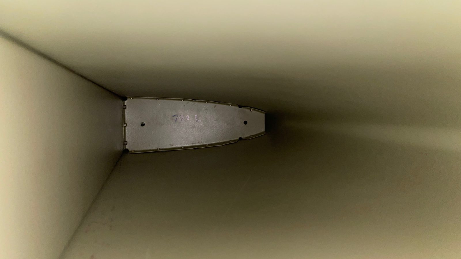
There weren’t many surprises this time around, however, a recurring issue with the tight quarters at the leading edge made for challenges with riveting again. After trying several different angle and positions, I found I was able to use the pneumatic squeezer to get one of the leading edge rib rivets in. Although once in, the rivet itself blocked using the squeezer to put in the one for the other side.
Really tight fit!
I ended up using an adjustable wrench as a bucking bar and the normal impact riveter to set this final rivet.
Speaking about riveting, I’ve had trouble setting what I felt were quality rivets. On the horizontal stab, I have a couple that are raised just a hair, so that you can feel the edge when you run your finger over them. Although it doesn’t present any sort of issue as far as build safety or part strength, it really grates on my O/C tendencies! Grrr!
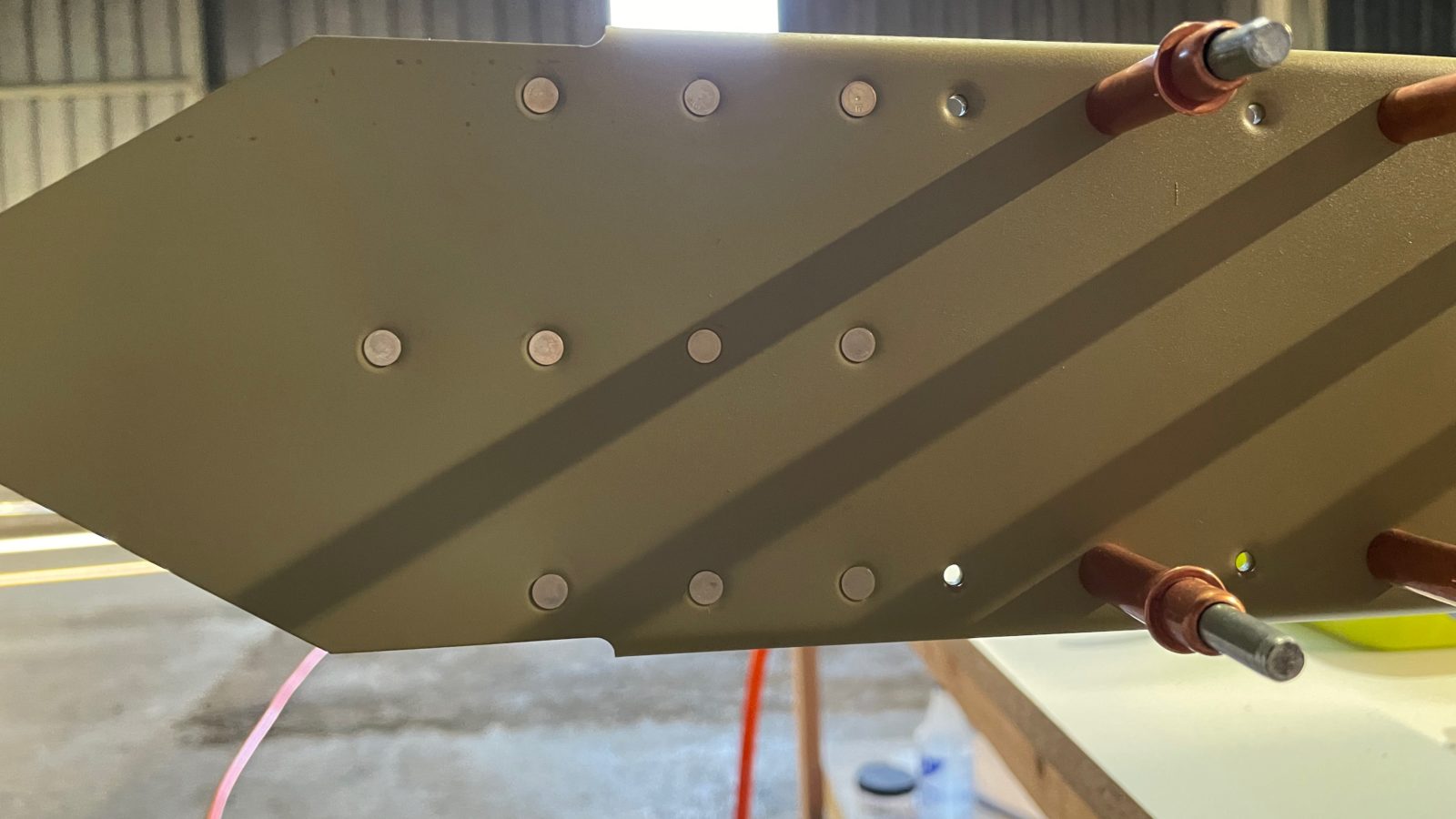
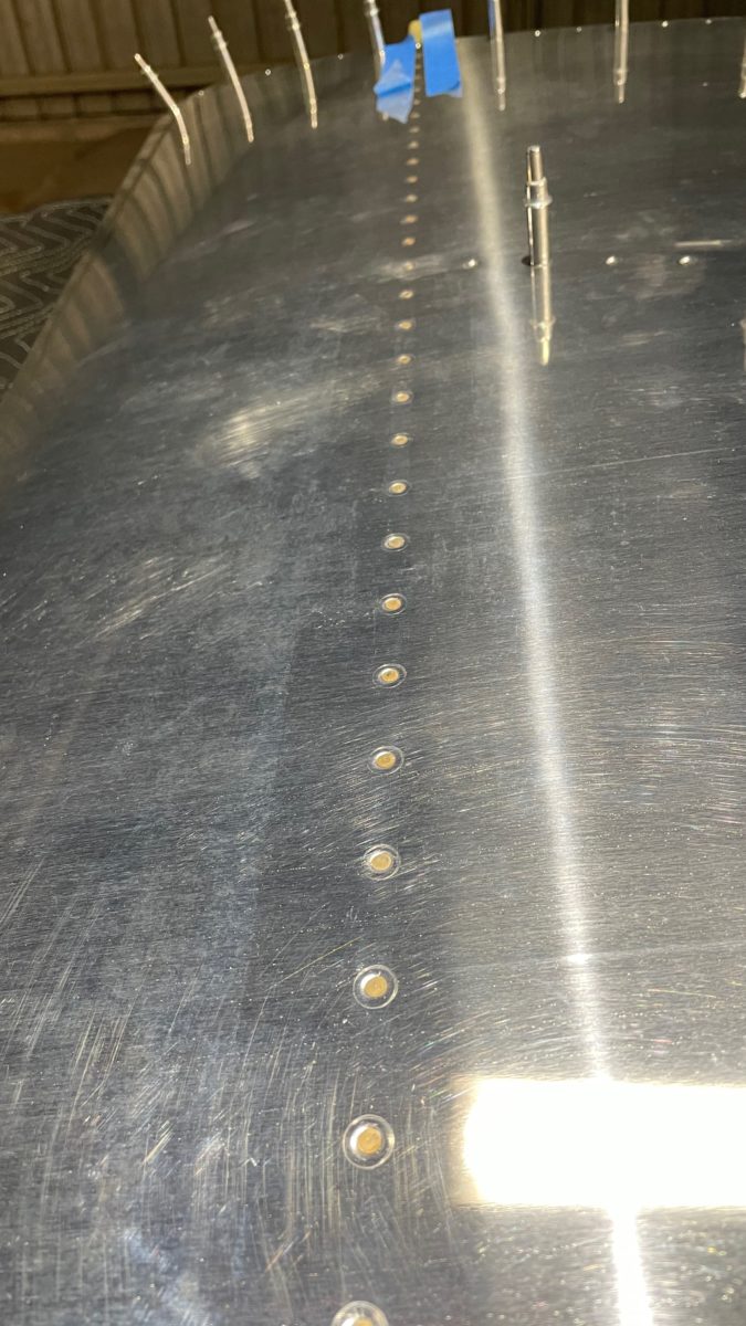
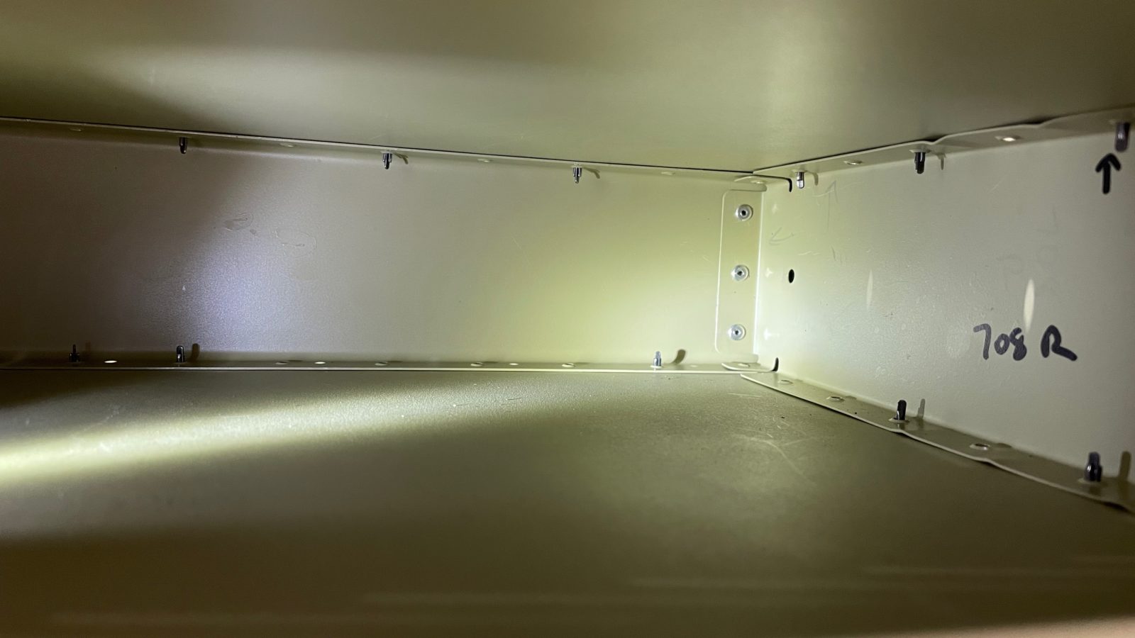
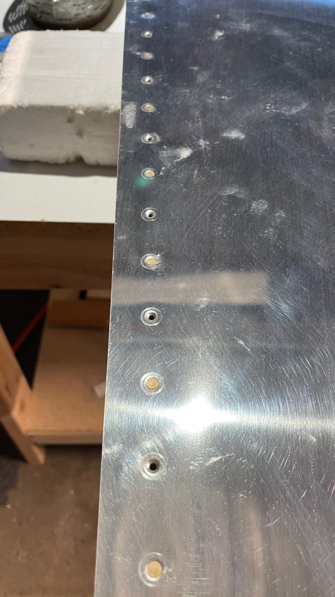
This time I started with what what has been my typical setup: ATS rivet gun with a flat mushroom set that has a rubber grommet around the outside edge, which is supposed to prevent making “smiles”, or indentations, on the side of the rivet. These are caused when you inadvertently lean the tool a little which riveting (doesn’t really work).
This time I decided to use another flat set that I bought. This one has a slightly larger diameter, and no grommet, so it fits completely flat against the rivet head. To keep from maring the surface, we usually lay down a strip of blue painter’s tape on either side of the rivet. The fact that the set is on a pivot keeps it from making the “smiles”.
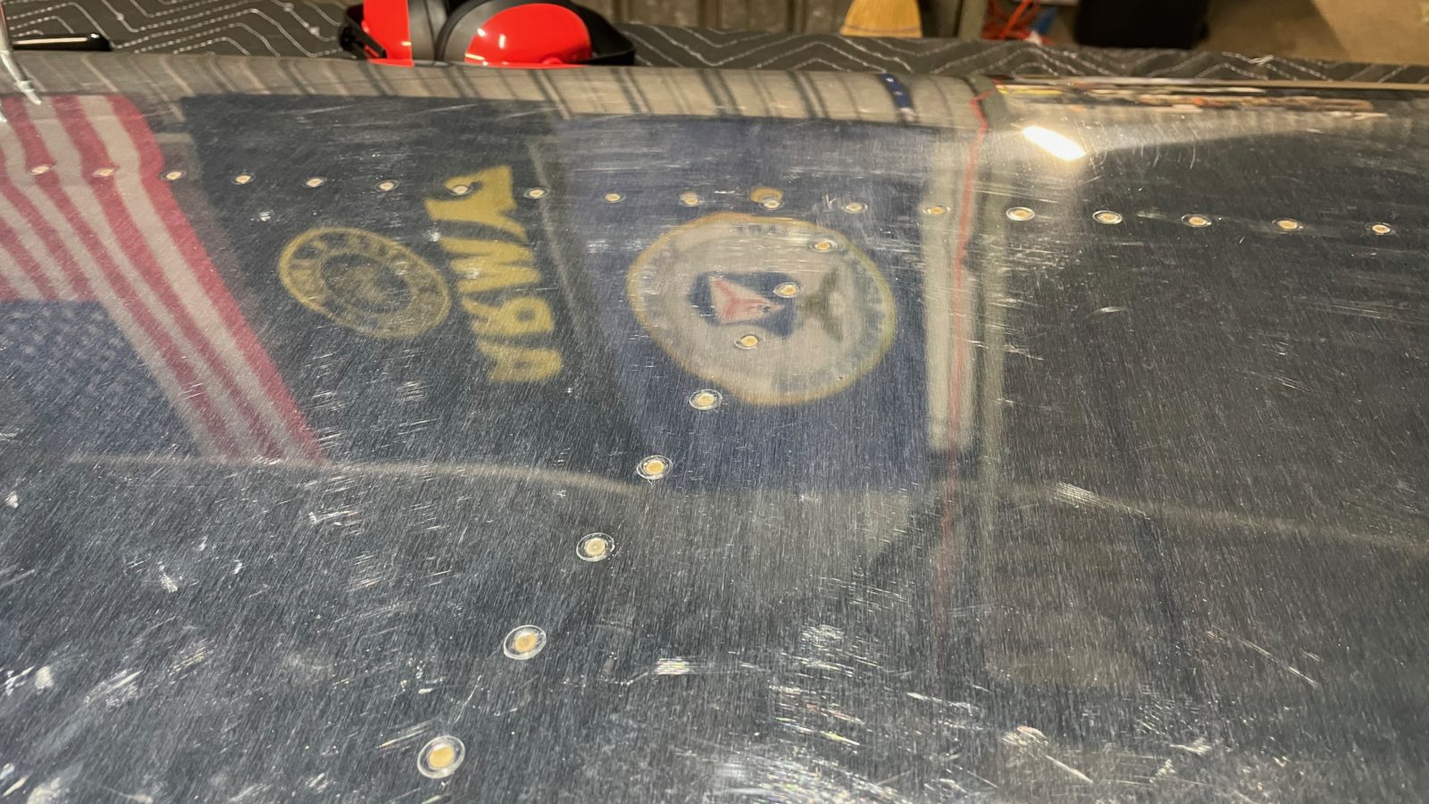
As it turned out, this works MUCH better for me! All of the rivet lines this time were perfectly flush. You can see it in the photos below. This is the new setup going forward. The only issue is that since the set is flat, it tends to wander around a bit while banging away on the rivet, so you have to be really careful to be perpendicular to the work.
Anyhow, we’re on to building the rudder and then the elevators next. For me, the challenge I see is bending the front edges into a rounded edge. This was one of the tasks during the training project that I felt I did terrible with. You basically use a forming tool (Van’s recommends a broomstick) taped to the edge in order to roll in a curve to the top side and bottom side of the airfoil, then rivet them together in the middle. I’ll be watching plenty of build videos to try to glean tips to make this successful!
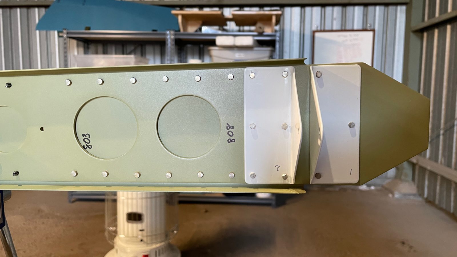
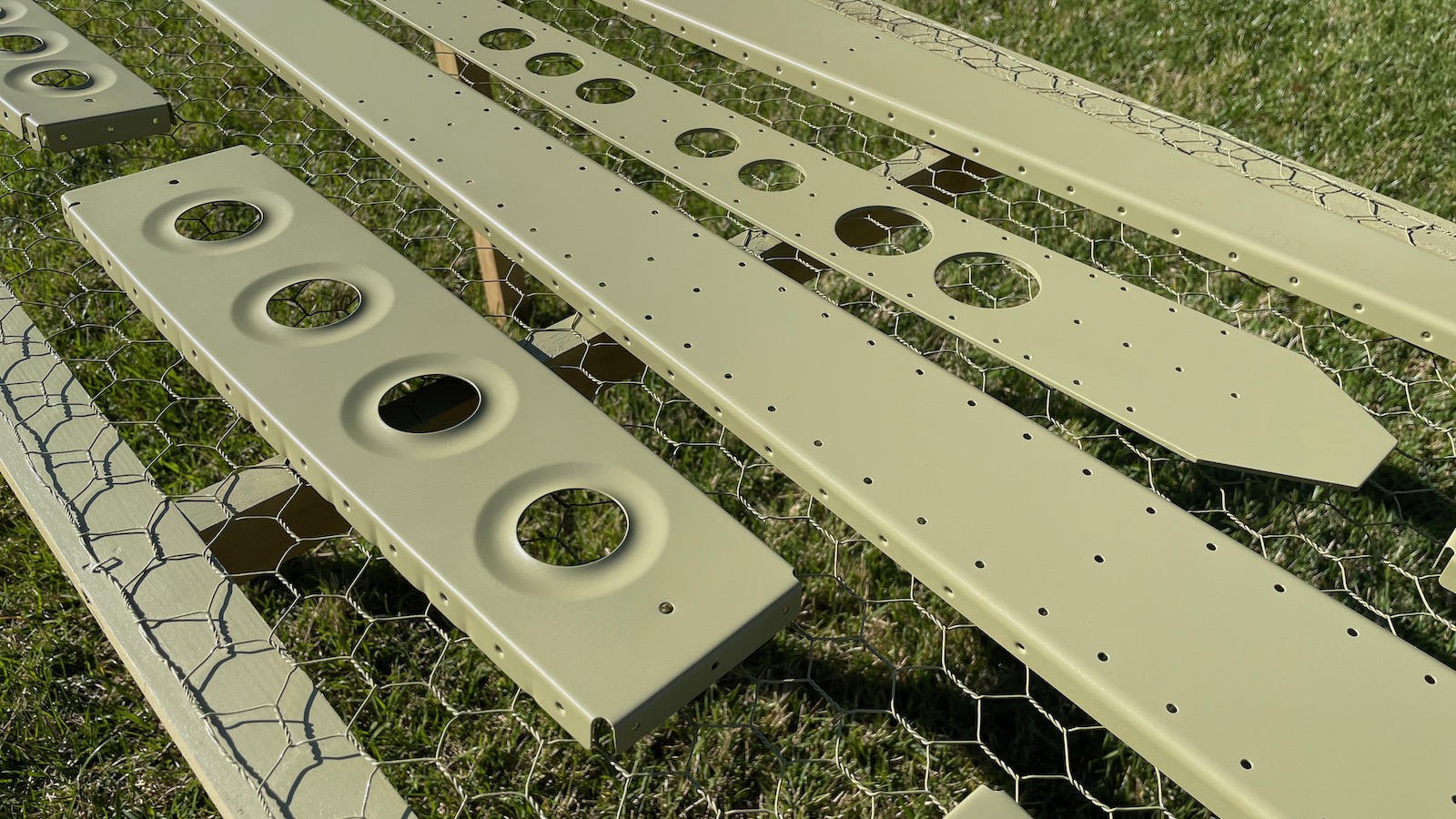
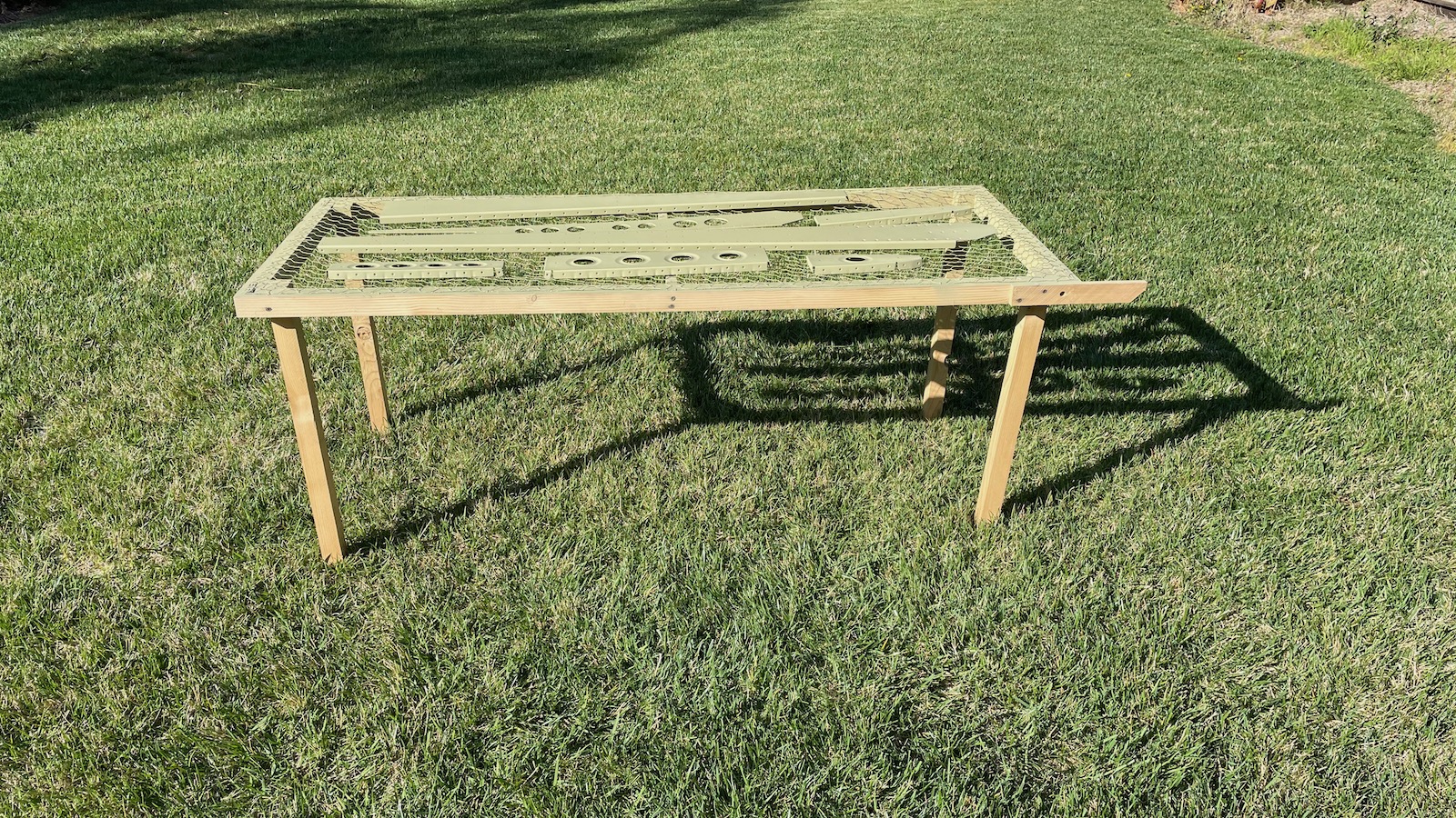
Having finished match drilling, deburring, dimpling and prepping the vertical stabilizer pieces, it’s time to prime them. I brought the compressor home and set up in the backyard again as before, laying out the pieces on the chicken wire paint table I made.
Freshly primed
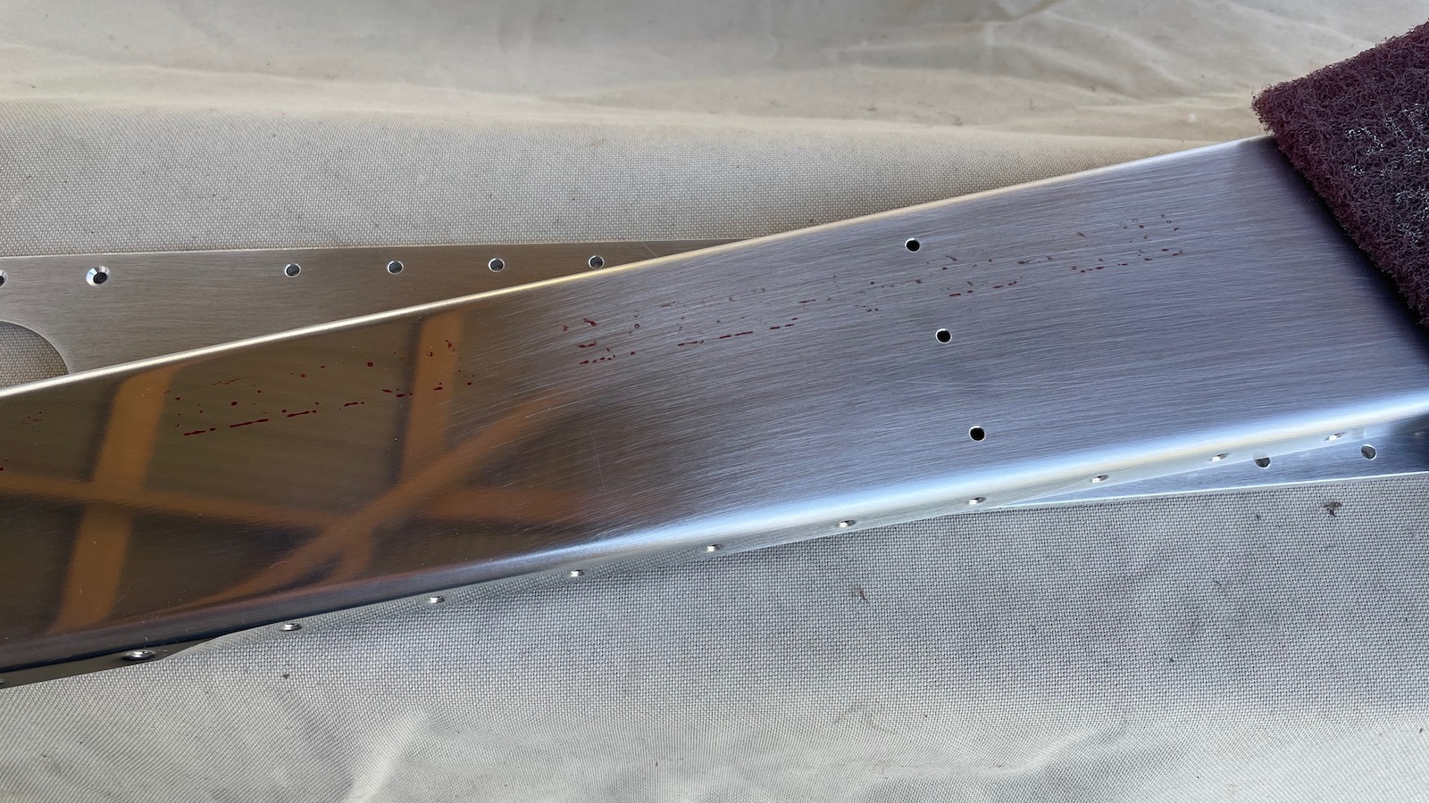
Before priming, each part has to be scuffed up to remove the corrosion-resistant alclad coating to make the paint adhere better. It turns nice shiny aluminum parts into dull, scratchy ones!
I’m always scuff-a-lin’
The skin was a bit tough to do, as it’s hard to get the spray gun close enough to the bend. This time the skin didn’t turn out too well. I think it was a combination of the way I had the gun set and the aforementioned distance. But, nobody sees the inside!
Next up is the vertical stabilizer. Together with the horizontal stabilizer, this makes the empennage, or tail, of the airplane. We’re working on the stationary parts of the tail. There are also control surfaces that need to be made and attached, which include the rudder, which attaches to the back of the vertical stabilizer, and the elevators, which attach to the end of the horizontal stabilizer. These move the plane in along the yaw and pitch planes (left-right and up-down).
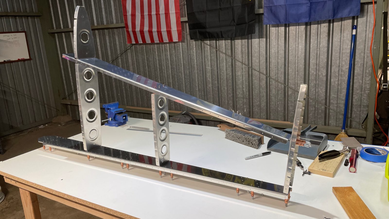
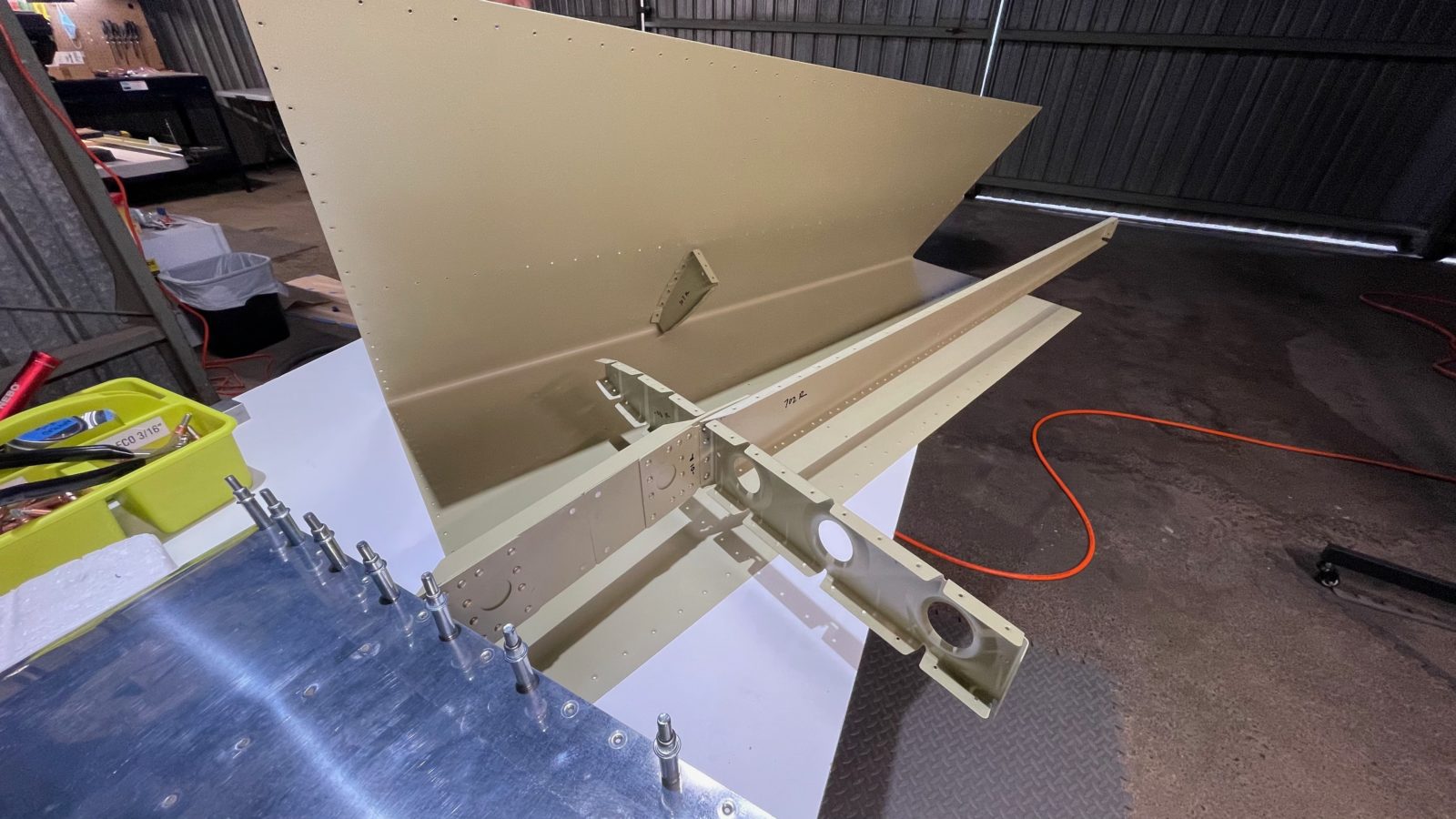
The first steps were, as usual, to cleco everything (except the skins) together, then match drilling all the holes to finish size.
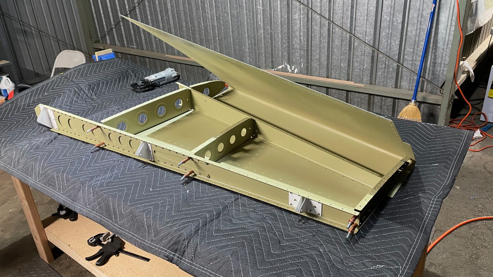
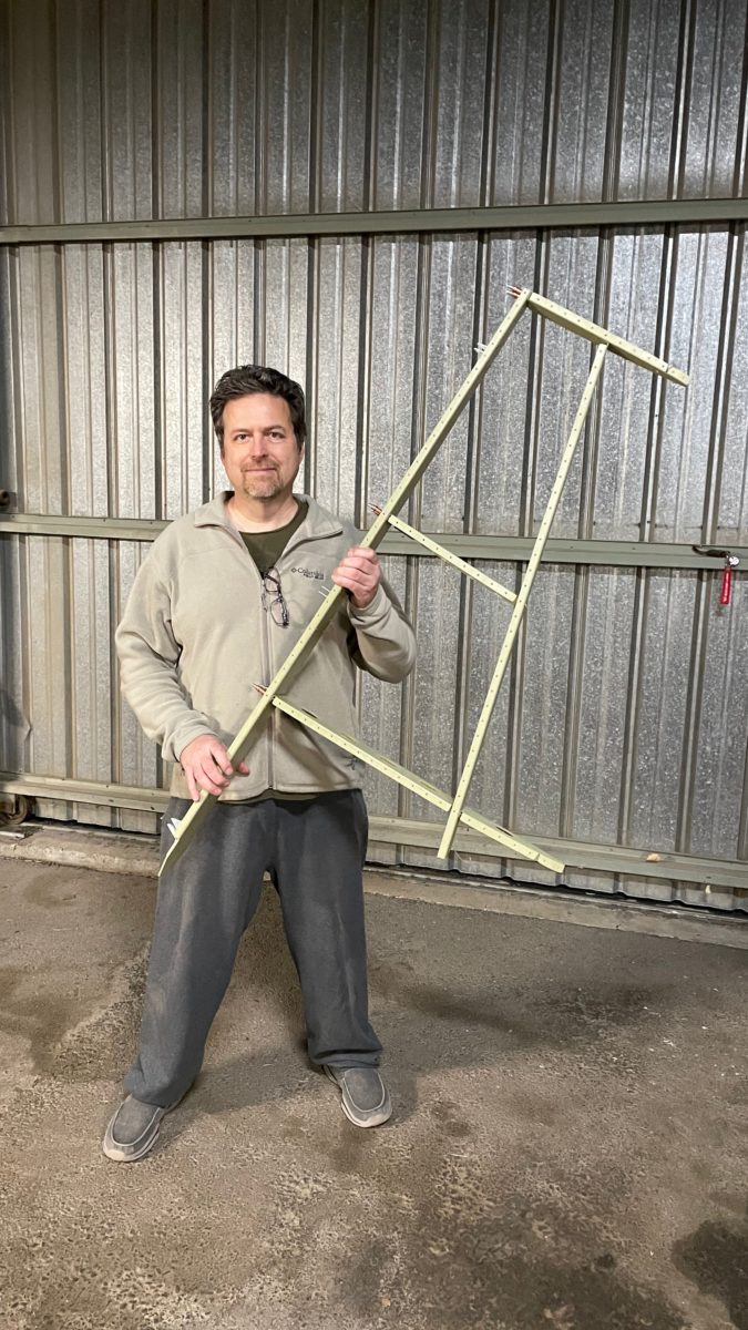
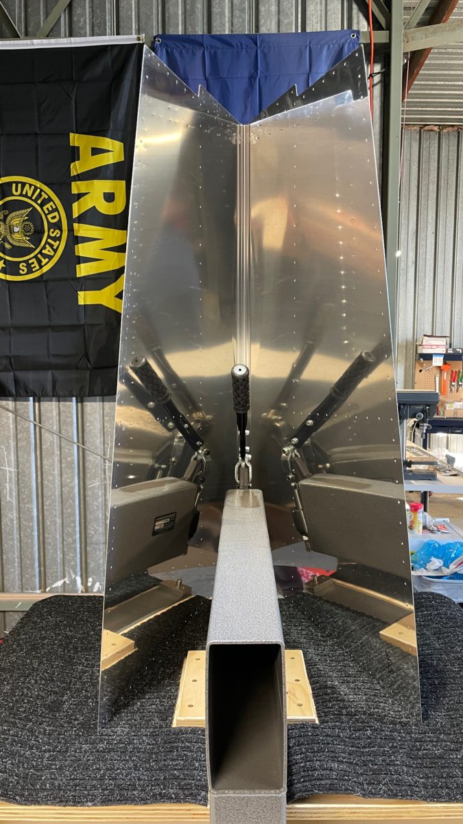
Dry-fitting the “skeleton” of the vertical stabilizer
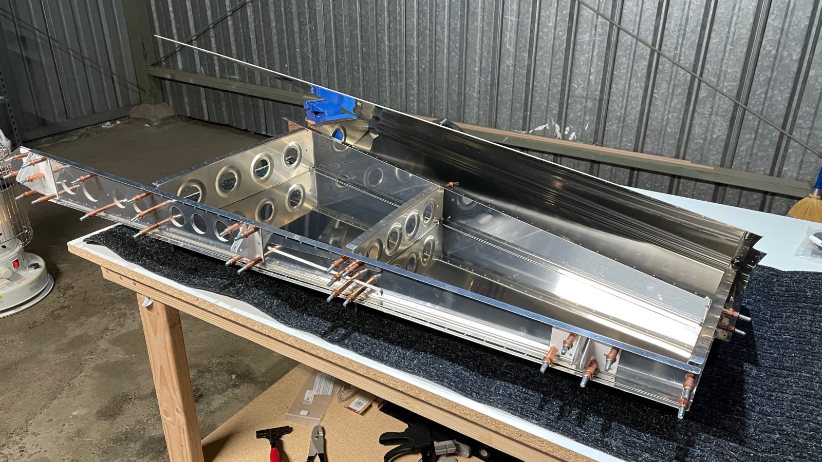
Once all the holes are drilled up to #30 size, next is to bring over the skin and cleco it on to the skeleton. This was a bit tough. The skin fits tightly to to the spars and ribs by design, so it took a bit of wrangling to get it “stretched” over the frame and cleco’ed in..
Harder than it looks
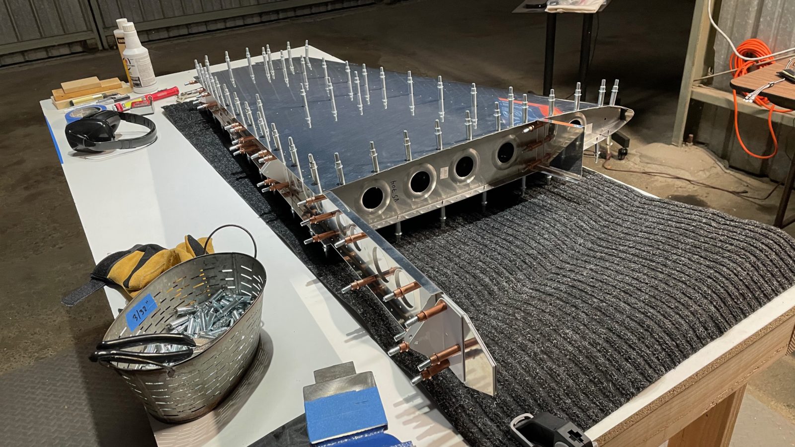
But with a good amount of elbow grease, the skin was attached and match drilled to #40-sized holes (the size required for 3/32″ rivets). After all the holes were drilled, it was time to take it all apart and deburr and dimple the skin-to-spars-and-ribs holes.
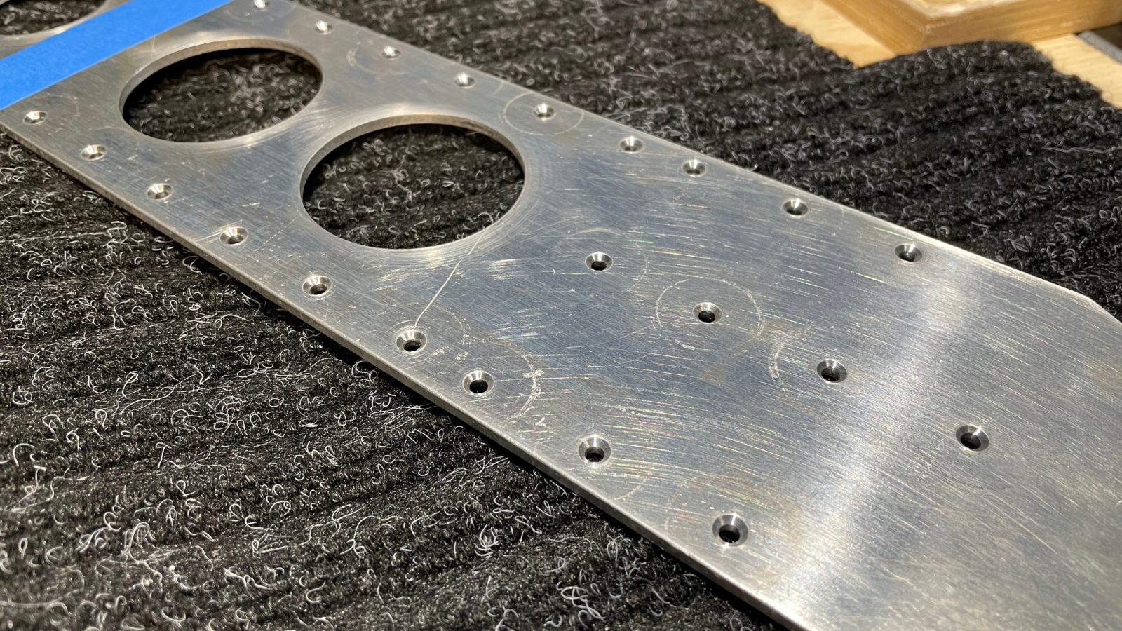
Final fit before disassembly and dimplingStop bit to limit how deep you drill your match holesDrilling down the skin
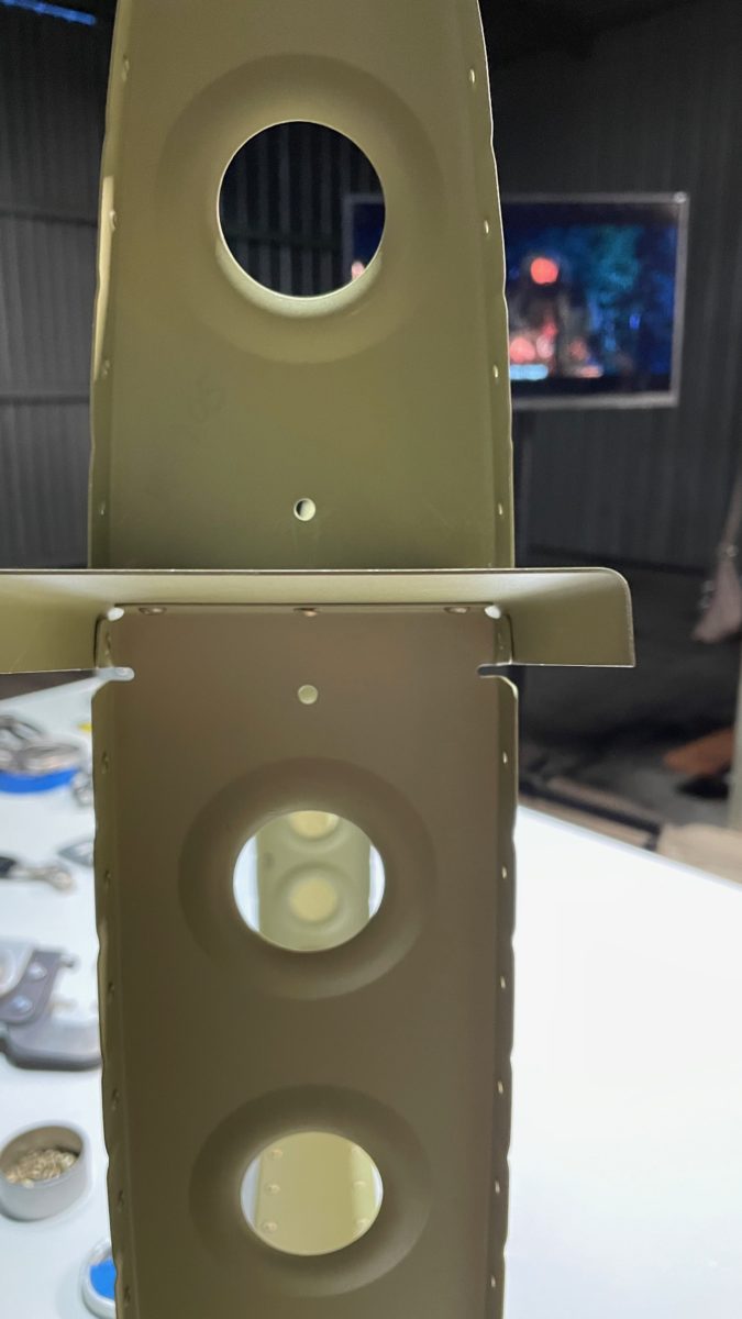
Part of the vertical stab needs to lie flush against part of the fuselage, so we have to use flush-head rivets like we do in the skins. Since one of the parts in the spar is a think doubler, we can’t use the dimpler…the metal is too thick. For this we countersink the dimples.
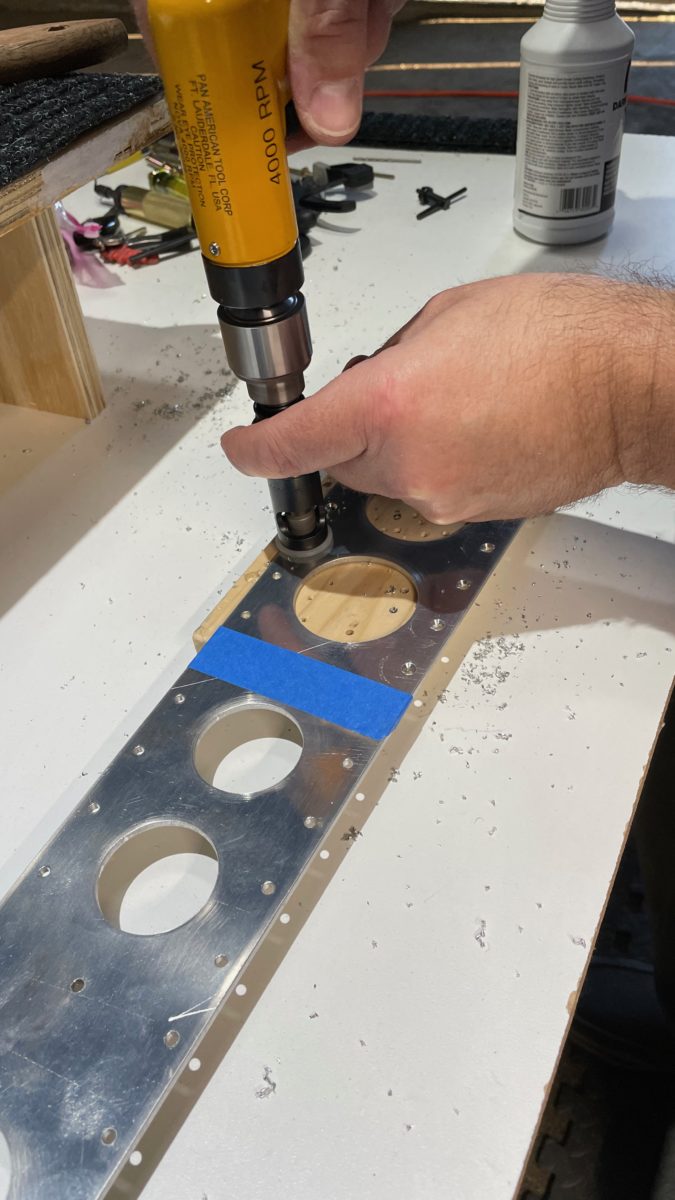
Machine countersinking the spar doubler, and using the dimpler on the skin
Last was deburring, which removes all the microscopic rough edges that the manufacturing process imparted by punching the parts. We also introduce burrs when we match drill. Now that we have a variety of deburring tools, this went quickly. With all the parts smooth and deburred, they were packed into the car for the trip back to the house, where I’ll prime them in the backyard.
“Congratulations! You’ve finished the first major sub-assembly on your new airplane.” Yep, feels good! Right there in the instruction manual, section 6, rev4, page 6-4, was this simple sentence that brought us our first “RV grin”!
So we’re at around 60 hours so far, and we’ve finally finished riveting the horizontal stabilizer. No rest for the weary tho, we moved right into starting on the vertical stabilizer, which should be a bit quicker (so far it has been). In fact, after a scant 6 hours of work it’s time to prime the pieces. Given, it’s not as large as the horizontal stab, but I think we’re becoming faster at the tasks: prep, match drill, deburr, dimple.
Here are a few photos from the work on the horizontal stab:
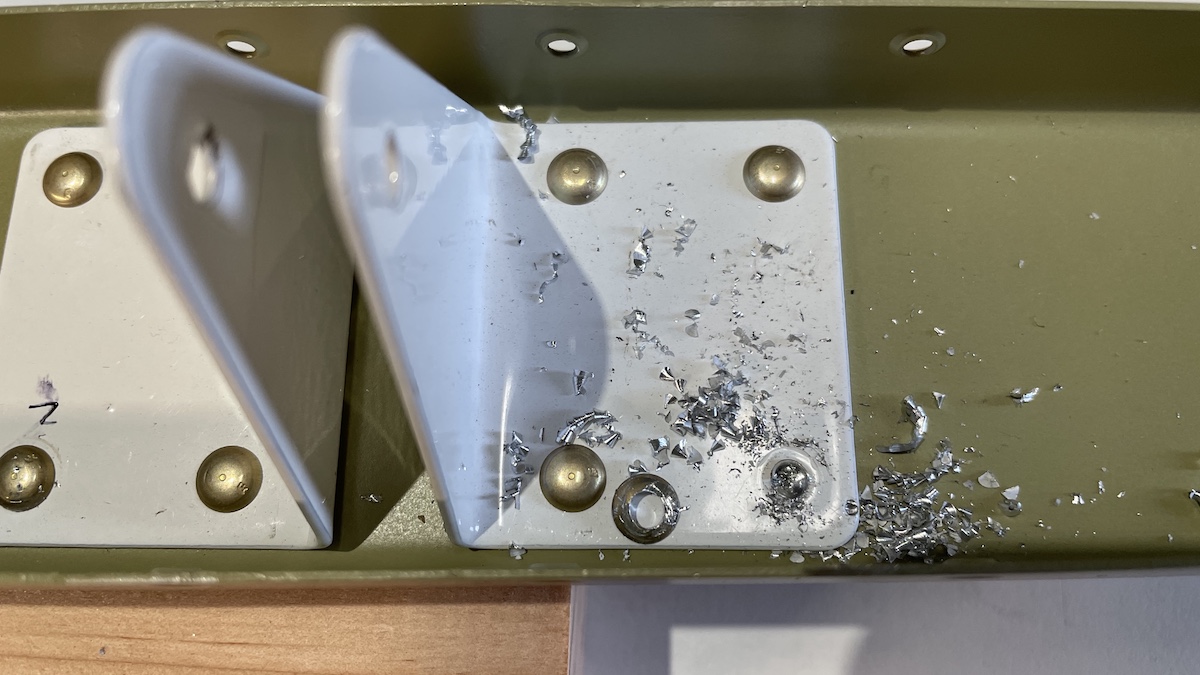
Getting to this landmark didn’t come without a couple issues. Driving the rivets nearest the leading edge was very tricky, and I didn’t use the right bucking bar, or maybe nerves got the better of me, and I left the rivet lifted a bit above the skin. I decided I wanted to remove one and re-do it, however by the time I decided this, the stab was mostly riveted closed. So, I had to remove a rib to get my arm in far enough to buck a replacement rivet. When I drilled out the rib, I inadvertently made a new hole!
Oops!
We decided to stop and get in touch with Van’s about what we should do. They told us that, since it’s not a critical juncture, we could go ahead and just re-rivet it, as long as the rivet wasn’t loose when we were done.
The second conundrum involved the final skin-to-spar riveting. Somehow the holes in the skin would not align with the spar holes. They were off by about 1mm, leaving any rivets I tried to place sit at an angle.
Holes won’t align!
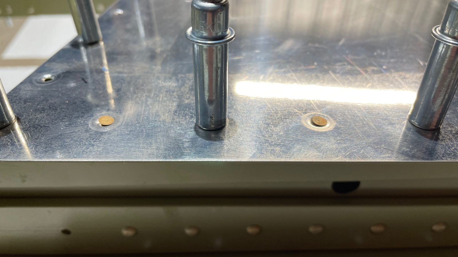
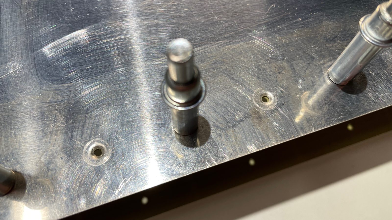
Van’s recommended using what looks like a marlinspike to “persuade” the two surfaces to align. I had a 3/32″ drive pin punch available, which did the same thing. Placing the pin into a hole, I tilted it over until the dimples for both holes “caught” and stayed aligned. Doing this about every 10 holes and the whole skin jumped into alignment. I could then place rivets into the holes and set them with the pneumatic press.
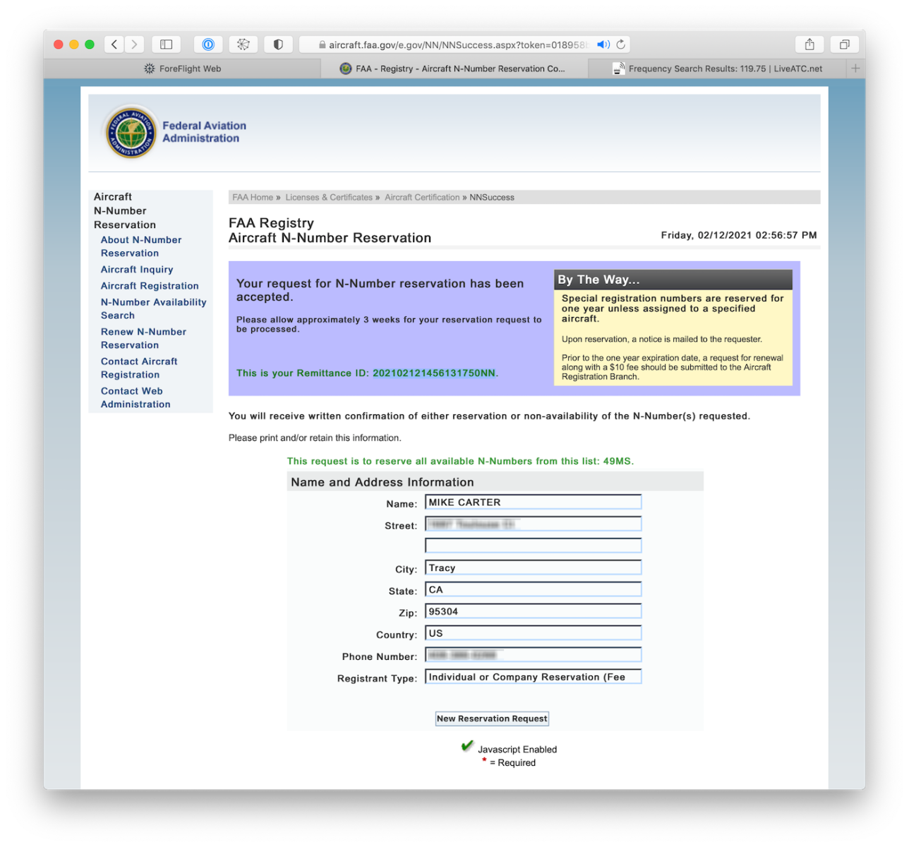
I was playing around with the FAA registration web site and decided to try a couple more combinations of what I thought would be a cool tail number for the RV. I had checked before and was a bit disheartened to learn that there are sleezy companies out there that snatch up all the small and cool tail numbers to re-sell them.
While some people might say that’s clever, I think it’s slimy. But that’s not what this post is about. I tried a number of “2×2” tail numbers just to find that they’re mostly all reserved (a few were actually assigned).
I did, however, come across 1 that was not yet snapped up by the sleazy businesses: N49MS. I immediately ran over to the wife to see what she thought. It consists of “49”, which reflects our 49-er spirit (since we’re Californians), and “MS”, which are our initials. Wow! I couldn’t think of a better way to personalize our airplane!
It costs $10/year to reserve an N-number. I’m hoping I’ll only have to spend $30 before I can turn the reservation into an actual registration. 🙂
I’ve crafted a couple simple tools to help us with the assembly of the plane as we go along, and I’ve decided to share them with fellow builders, so I am putting up the 3D STL files on my Thingiverse page for people that have a 3D printer and would like to print them.
For those that don’t, I put together a little where you can purchase the designs I made which are printed or laser cut already. You can find my first design, a pneumatic squeezer gap gauge, on the Aviate.Org Online Store.
There’s also a donate button there if you’d like to buy us some coffee…or better yet…100 rivets!
I’m quite happy that after completing the reveting on the rear spar, there were only 3 rivets that I wanted to replace…2 of them for sure, and 1 that probably could have stayed. I ordered a rivet removal tool, which is specifically for universal rivets (round heads). It was another good buy!
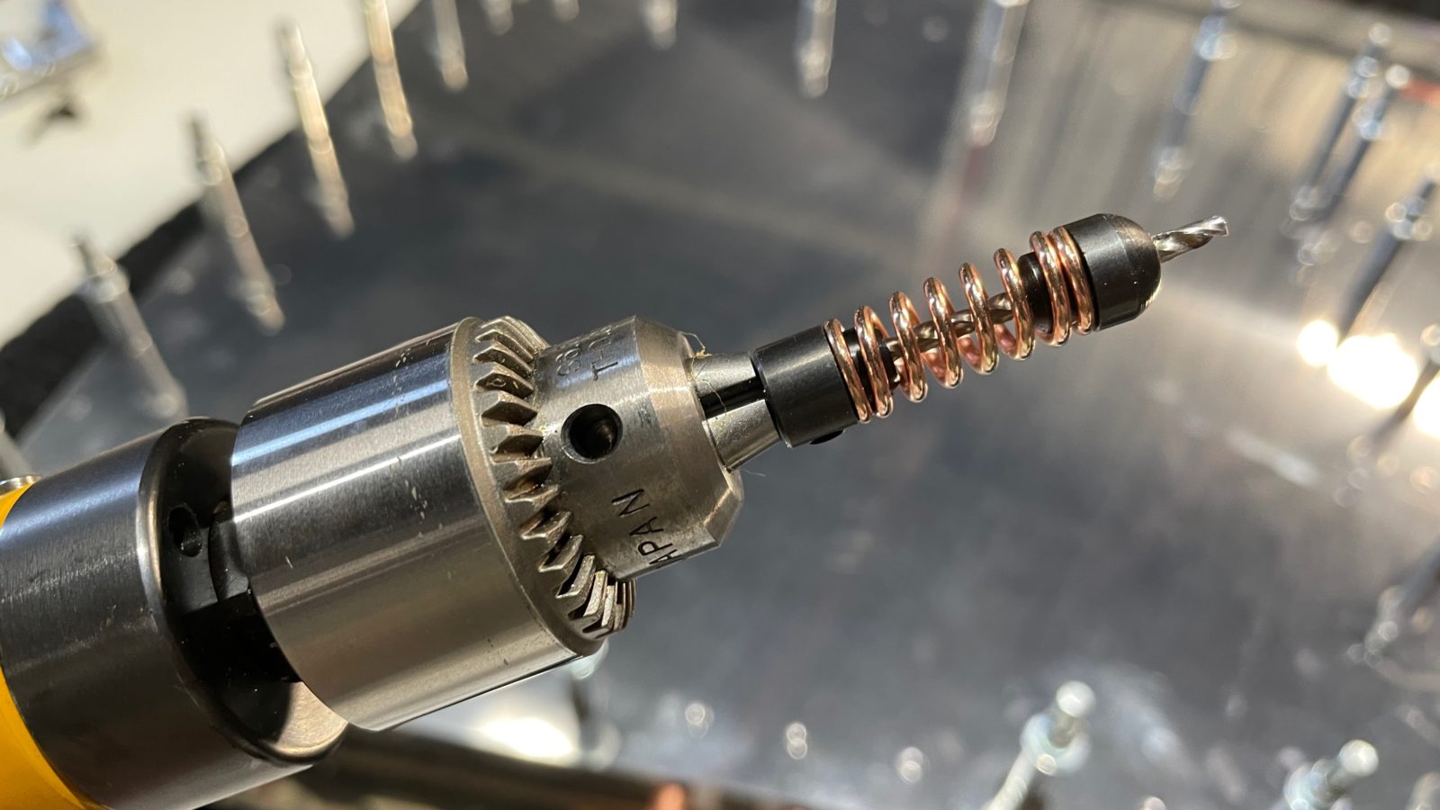
Rivet removal tool
The tool attaches to a drill and has a drill bit which travels through the center. A spring keeps it retracted. The end of the tool has a recess that allows it to fit completely over the rivet head, and the drill bit travels through a hole in the end, thus keeping it centered on the rivet. Without this arrangement, it’d be very hard to drill perfectly in the center of the rivet (given the sloping head).
Drilling in the exact center is important, so that you don’t accidently drill and deform the underlying rivet hole. You can set the depth the drill bit extends through the end of the tool as well. The goal is to drill just beyond the surface of the skin. You then use a punch in the hole you just drill to snap off the head of the rivet, then punch out the bottom.
Another rivet out. the snapped-off head it just to the right of the hole.
Front Spar
On the front spar, we couldn’t use the pneumatic squeezer for the bulk of the rivets since they sat behind a rather tall set of angle brackets. So, I broke out the rivet gun and bucking bar, and went old school for most of them! They turned out better than I thought they would given I’ve been spoiled by using the pneumatic squeezer for most the riveting of the spars.
Now the clock starts! Fulfillment time currently is 14 weeks. I’m hoping that we’ll be done with the empennage just before the wing kit arrives. From the looks of it, 2 large crates comprise the thing, and there are a few of the larger fuselage pieces thrown in to take advantage of the room.
Tomorrow we’re going to have a nice chicken wing lunch to celebrate!