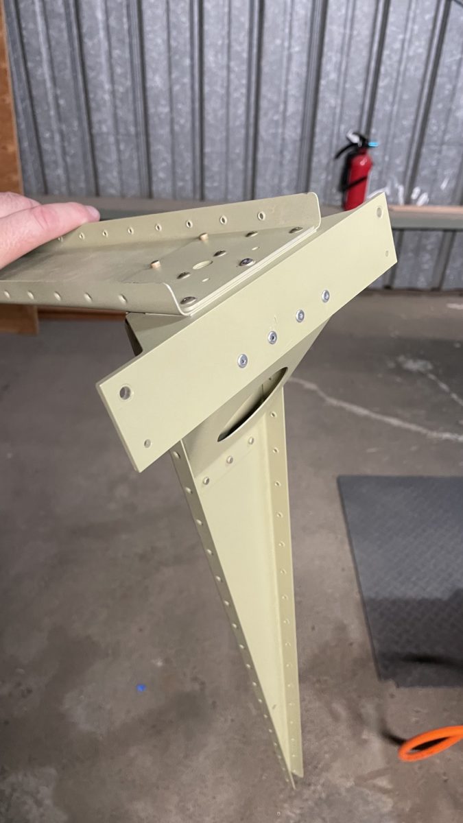
Today we brought back all the rudder parts that we primed in order to start the assembly. There aren’t that many parts in this phase. The biggest ones–the skins–were prepped in an earlier stage and are waiting to be mated to the “skeleton”, which is what we’re working on today
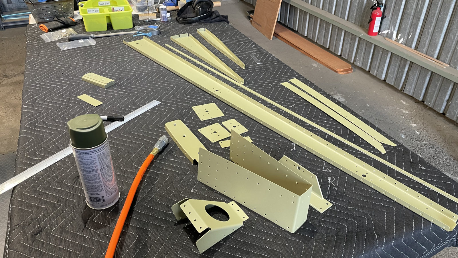
I did not prime one of the parts, a bracket known as R00001, because it was not in the instruction sheet, but instead called out on the plans. That’s why it’s really important to read BOTH the plans and the instructions to make sure you don’t miss anything.
This part was also not where I’d expect it, in a baggy with all the nuts, bolts and other paraphernalia required to assemble. In fact, when I saw it on the plans, I began to manufacture it until Sheila found it in the bag of parts. Fortunately it’s already punched and cut. I just needed to prime it. This was the first test of the primer rattle cans I bought for just such an occasion.
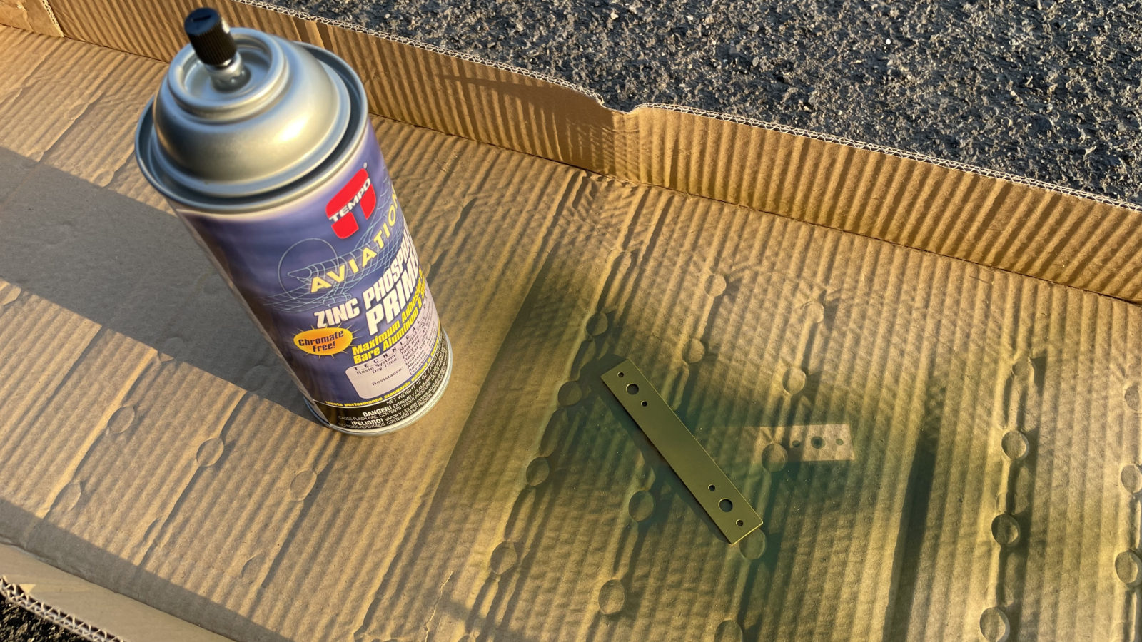
This worked out okay, but remained tacky for a LONG time. With AKZO I can handle the part within 15 minutes (usually dries to the touch in 5). With this stuff, it was tacky an hour later, when I could no longer wait for it to dry. This’ll definitely be a last resort. I *do* have a small paint gun I keep at the hangar. Maybe next time I’ll mix a bit more AKZO and bring it along to touch up anything.
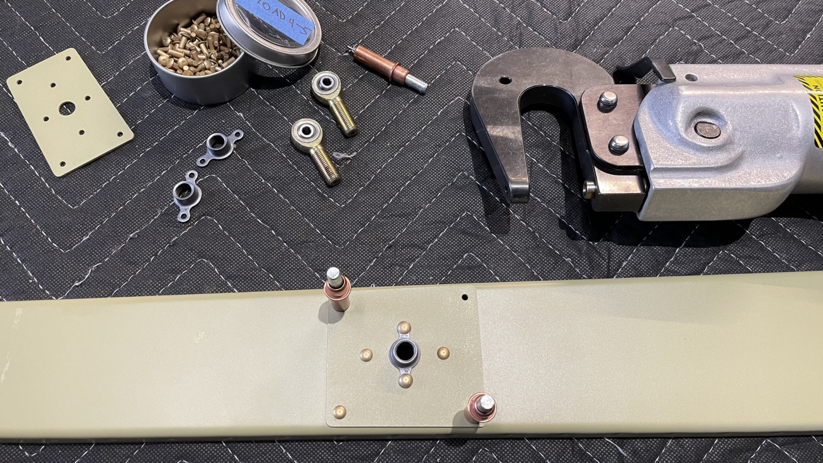
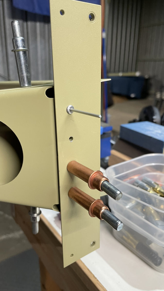
First up was riveting the reinforcement brackets for the vert stab attach points. Easy peasey. Next up was attaching the counterbalance rib, then the counterweight. That was okay as well, however it was there that I noticed I primed both sides of the counterbalance skin, which means there will be one part of the airplane that will be green. :/ I was a bit disappointed, but it’s not the end of the world.
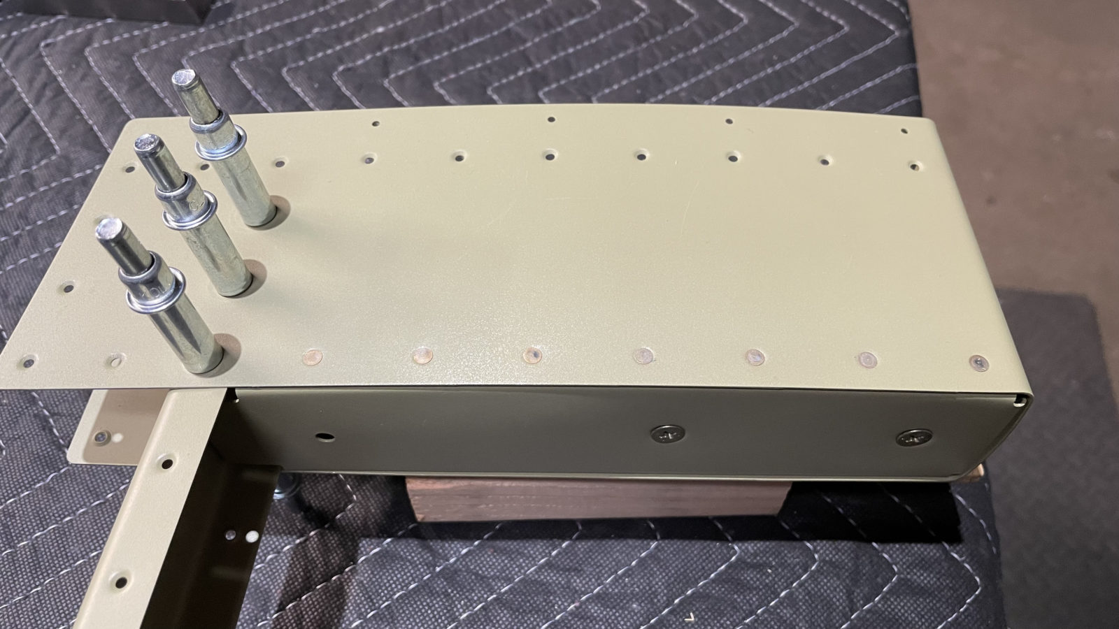
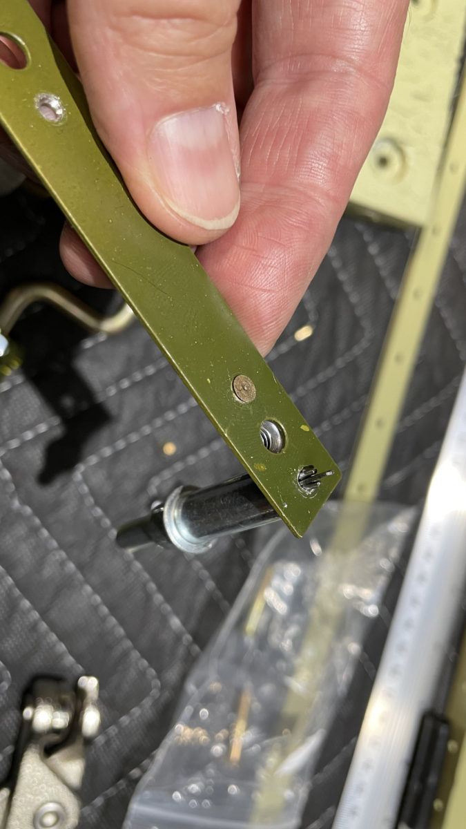
The assembly of the bottom of the spar went okay. However it did take a bit of puzzling to arrange for the riveting order…it’s a complex assembly. I bolo’ed the first rivets in the lower reinforcing plate. Not sure why I was smearing them so badly. I drilled out 2, but kept the center one in place. It doesn’t look that bad, and there are 11 rivets holding that plate in place. One questionable one isn’t going to amount to anything. This is probably what happens when you go a long time without using the rivet gun. I’ve grown soft relying so much on the pneumatic squeezer!
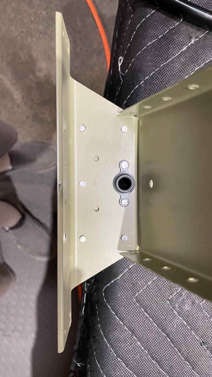
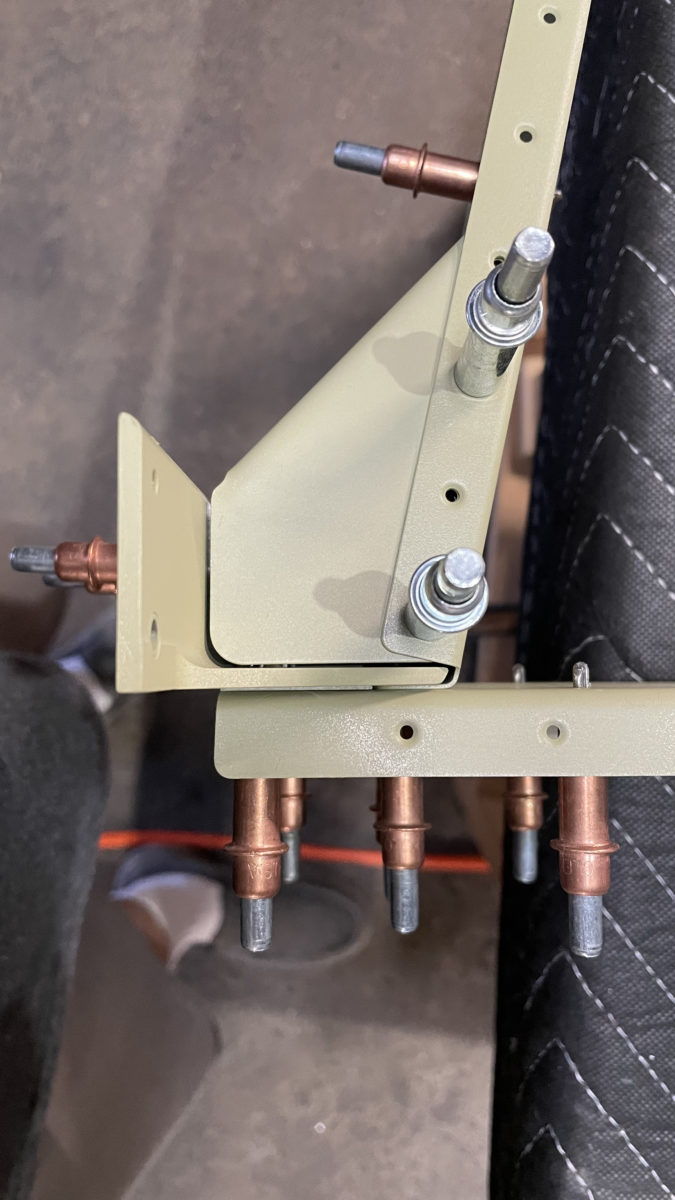
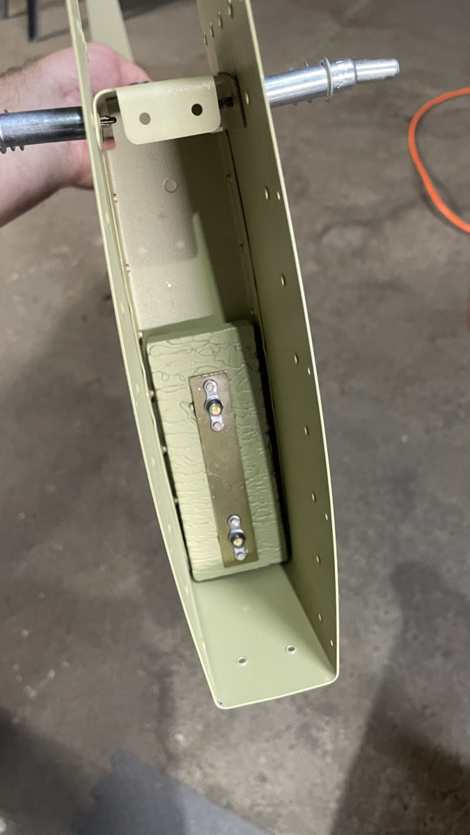
I elected to go with pop rivets for the final connection. It was too weird and awkward trying to get even the smaller bucking back inside the cavity of the horn brace. I technically could have done it, but based on my riveting performance, I figured I’d just botch it up good. So, 4 more LP4-3 rivets were deployed!
It’s still warm out, so we’re starting work later in the afternoon, with just a 24″ fan to keep the air moving. I may purchase a swamp cooler for next summer so that we can work a little longer. We’ve also started working on Thursdays along with the weekends, as I want to ramp up the number of hours per week we’re working.
Next up is attaching the skins to the rudder frame and preparing for the critical trailing edge work, which will involve drilling a heavy duty angle iron I picked up from Home Depot, to which I will glue up and cleco the leading edge to. This is done to make the trailing edge as straight as possible. No more than 1/10″ bow permitted across it’s length!
After that comes the leading edges, which we’ll roll with a 1″ wooden dowel and pop rivet. I’ll get to use my new pneumatic pop riveter and edge-forming tool!
Testing