Tonight we’re back at it, working on finishing up the rudder. We’re at the point now, with the skins finished and primed, where we connect up everything and check for fit, then match-drill all the holes, deburr and dimple, then bring the remaining pieces home for priming. Total time tonight: 6 hours.
We ran into a couple small issues, which I’ll either ask the community or Van’s about. Here’s the entry from our EAA builder’s log:
Resumed work on building out the rudder. Work included assembling the rudder, match-drilling, deburring, dimpling ribs and spar. Issues: nothing in instructions about drilling the R-710 rudder horn brace, but it seemed like this was the time to do it. Notch in skin was misaligned with R-405PD rudder horn on 1 side. Will probably widen the slot in R-901 skin to accomodate. Lastly, looking for guidance on drilling/dimpling the top row of holes on the R-913 counterbalance skin. Instructions just say to match drill, deburr and dimple the 913-to-901 holes. Looking ahead, the attachment of the rudder tip, R-909, will use similar process to detail B-B on drawing 6, but I can’t find the instructions on when to accomplish that. Seems appropriate to do so before priming.
https://eaabuilderslog.org/?s=mcarter
I think I’ll probably just widen the slot in the skin so that it doesn’t stress so much…
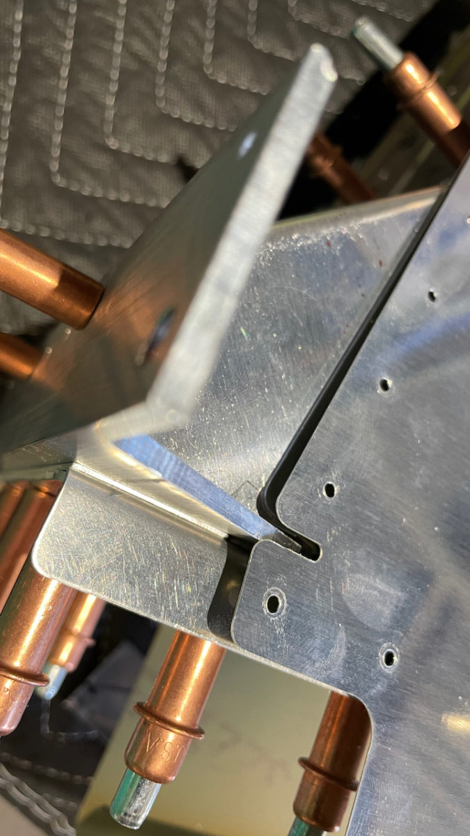
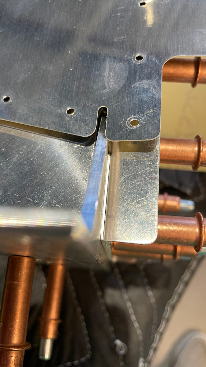
It’s only happening on 1 side, but it’s kind of weird. That’s a fairly good-sized misalignment.
The other thing was that there was no indication in the instructions that we needed to drill through the R-710 horn brace while match-drilling the skin to the spar. It may have just been inferred from the other work, but I think the instructions mentioned all other pieces _but_ the brace…
Trim the excess material from R-710 rudder brace. Fit the R-710 between R-405PD and R-904. Cleco the aft edge of R-710 to the bottom of R-904 and drill #30. Match drill through the forward edge of R-710 using the holes in R-405PD as a drill guide.
– From the manual.
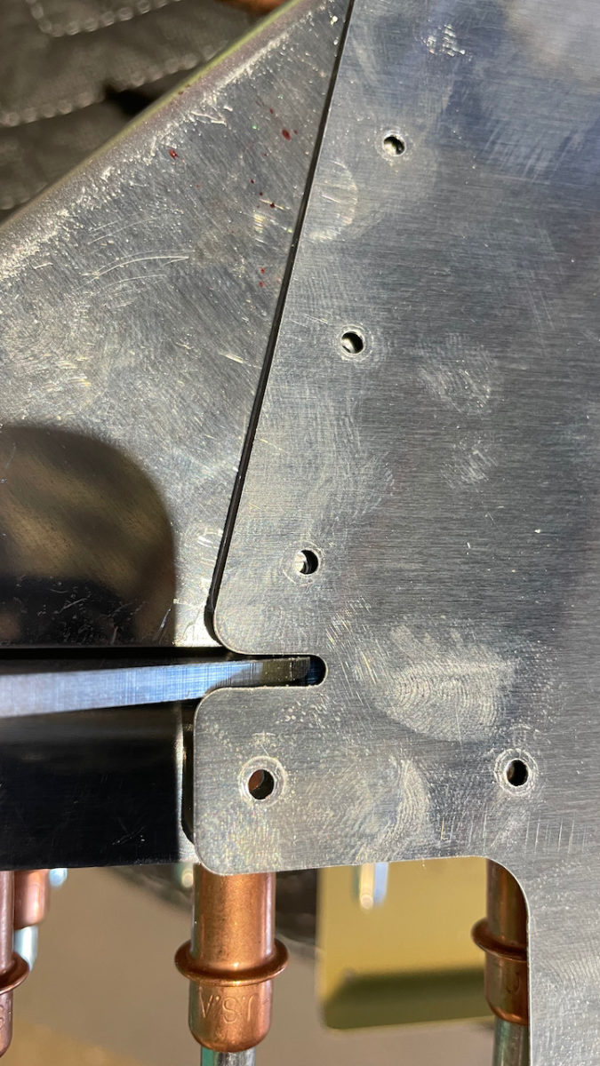
This is the only place in this set of steps that the R-710 is mentioned, and the match drilling is only for the three holes between the brace and the inside of the spar, not the flanges of the spar to which the skins are attached.
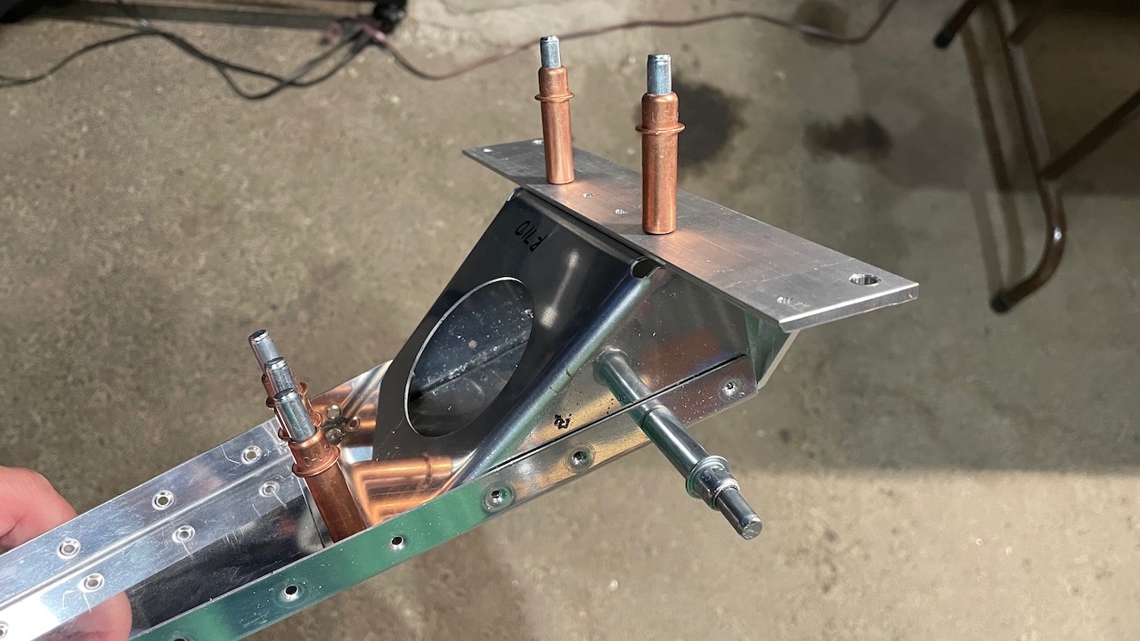
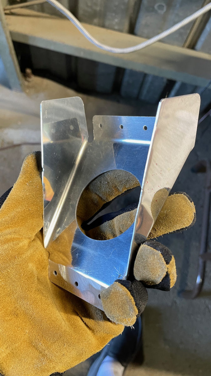
As you can see here, there are 4 holes where the horn brace sits behind. You obviously can’t rivet the skin to the spar if there aren’t holes and dimples in the brace! So I went ahead and drilled and dimpled the sides of the horn brace so that they can all be reveted together.
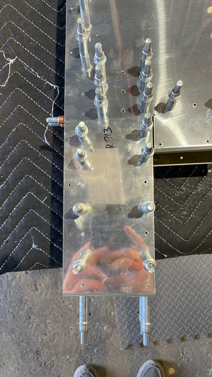
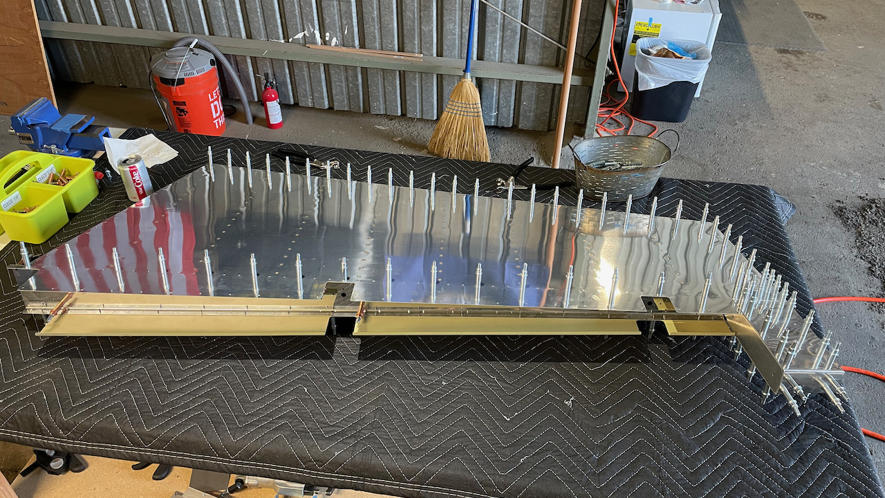
Lastly is the counterbalance skin, which sits at the top of the rudder, atop the skins…
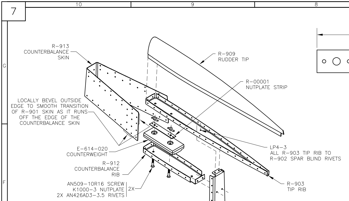
Here, we’re told in the instructions to match drill, deburr and dimple all the holes in the counterbalance skin where it meets the main skins (R-901s), along with the ribs and spar. That doesn’t include the top 10 holes (5 each side), which will be used to secure the rudder tip.
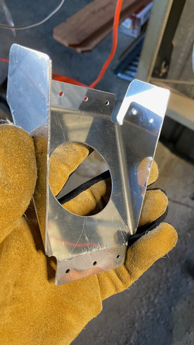
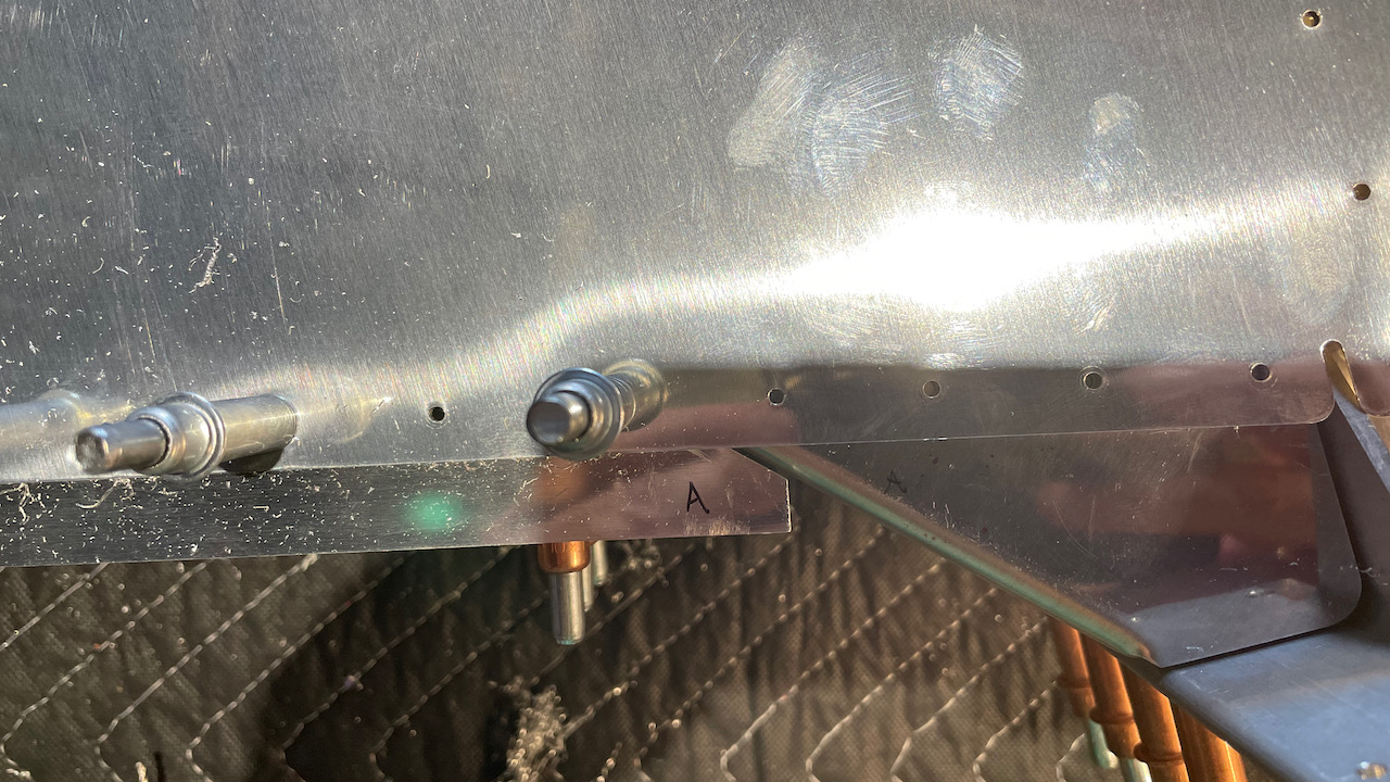
First off, this was a pain to attach to the ribs! it’s fairly thick, and there is a sligh bow in the end, which matches a slight bow in the ribs. You can see the bow in R-903 and R-912, where it attaches to the counterbalance skin. The first time I tried to cleco everything together, it wouldn’t work. Tonight, it worked. Weird. I did use a small awl to help “fold” the skin over the ribs and get the holes aligned. Good, tight fit, that’s for sure.
So what to do with the 5 holes along the top edge? There is no guidance in this section on what to do specifically. I think it’d be easy to go ahead and assume you have to match drill, deburr and dimple them along with the rest..which are all #40…but that’d be wrong. Here’s what the instructions say:
Cleco the R-913 counterbalance skin to the R-903 tip rib and R-912 counterbalance rib. Match drill #40 the counterbalance skin to the ribs using the pre-punched holes in the R-913 counterbalance skin as a drill guide.
– From the manual.
The issue is, if you look ahead to see just how the R-909 rudder tip attaches to the counterbalance skin, it uses a larger hole and dimple! The instructions don’t directly mention that, although the plans do plainly show a CS4-4 is required. It does say to match drill the skin to the ribs only. A few steps later it say, “Disassemble the rudder and deburr all the holes. Dimple the skin, spar and ribs.”
Technically, the counterbalance skin is a skin. If you were to go ahead and dimple all the holes, that would include those top 10 holes. However, that’d cause an issue later when it becomes evident that you need to use a CS4-4 rivet for the attachment of the tip, which requires a #30 hole. If you had already drilled/dimpled the hole for #40, you’ll need to rework it later, which could weaken the aluminum. So I’m thinking we should probably drill those top holes in both the 913 and 901 skins to #30 now instead of later. Weird how the holes are pre-drilled for #40 tho. I think I’ll bring this up to Vans.
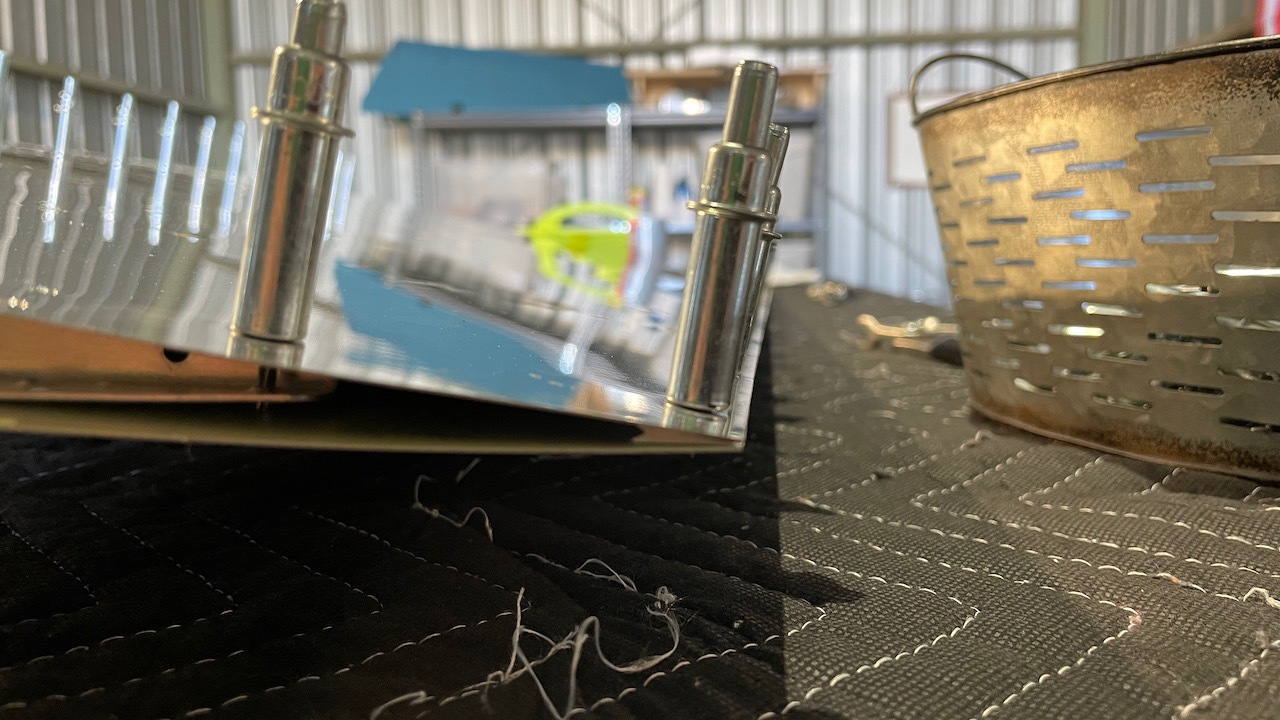
Here are the rest of the pics from the night: