It’s been a while since I’ve posted here, mainly because I’m documenting the build on the EAA Builders website primarily. It’s that website that will contain all the “evidence” I need to show the FAA when I’m ready to petition for an airworthiness certificate. It details all the work, along with images. However, I like to keep this site around just for my personal musings (and for anyone interested in the process).
We finally finished the empennage kit in November! The empennage includes the “tail”. This equates to the vertical and horizontal stabilizers plus the control surfaces thereupon (elevators, rudder and trim tab). It’s the first of the 4 major kits in the plane (5 if you count the “firewall forward” kit).
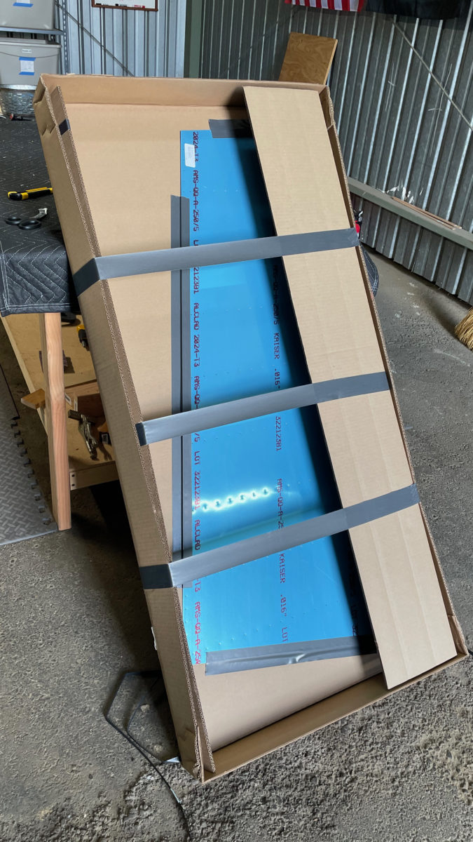
Now we’re on to the wings. We’ve had the 2 crates that contain all the parts for the wings sitting in the hangar for a year now, and I was a bit anxious about what I’d find inside. Fortunately, no major corrosion! This was my primary concern. We did the inventory, and stashed new parts on the shelves. We were both surprised at how few parts go into the wings. It’s also the quickest kit of the build, with the next one (fuselage) being the longest. Still, we’ll probably take just under a year total to complete it. I’d love to be able to do it faster, if we can.
Van’s Aircraft, the kit provider, filed for Chapter 11 bankruptcy protection this week. They’ve found themselves in a bad financial state after a number of issues. Among these were COVID, then a surge of kit interest, some technical problems with third party contractors (bad primer), and mismanaging the huge increase in demand.
As part of that last point, Van’s decided to laser cut some of their kit parts. This ended up producing stress fractures in some of the parts, which of course is never a good thing. Although a lot of parts are still safe to use, it caused a lot of commotion among kit builders, and Van’s had to conduct additional research and testing to find which parts need to be replaced.
Chapter 11 isn’t a death knell, in and of itself, and the team they hired to help them through the process are confident Van’s will come through it unscathed. They are still formulating the required plan of action to get them back to profitability, so not sure yet what the impact to us builders will be. Most definitely it’ll involve price increases. It’s a shame, but as many builders have said, “Build on!”
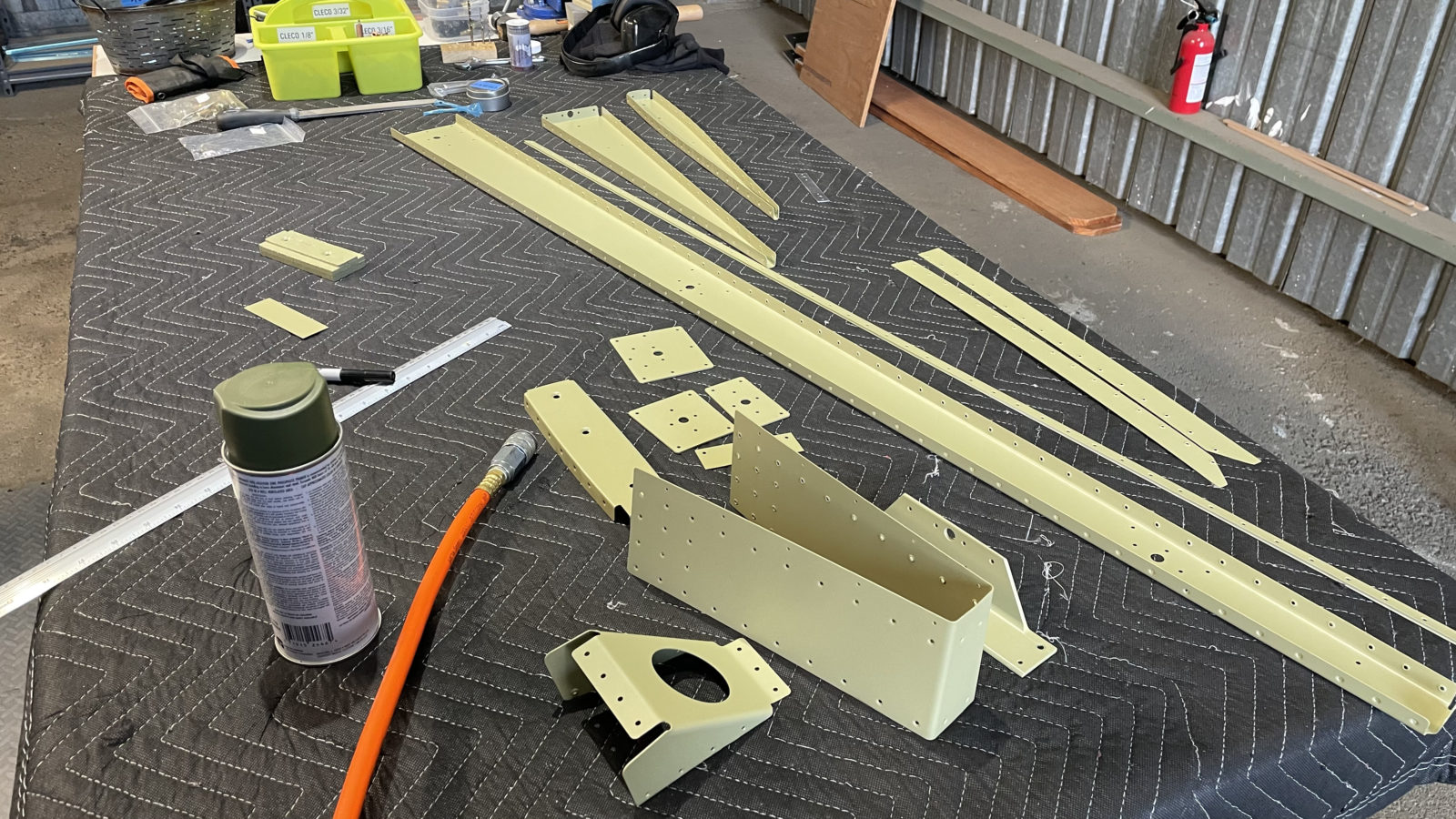
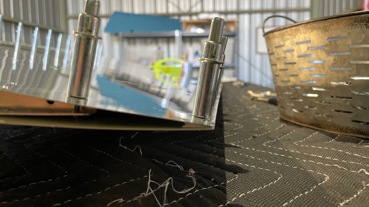
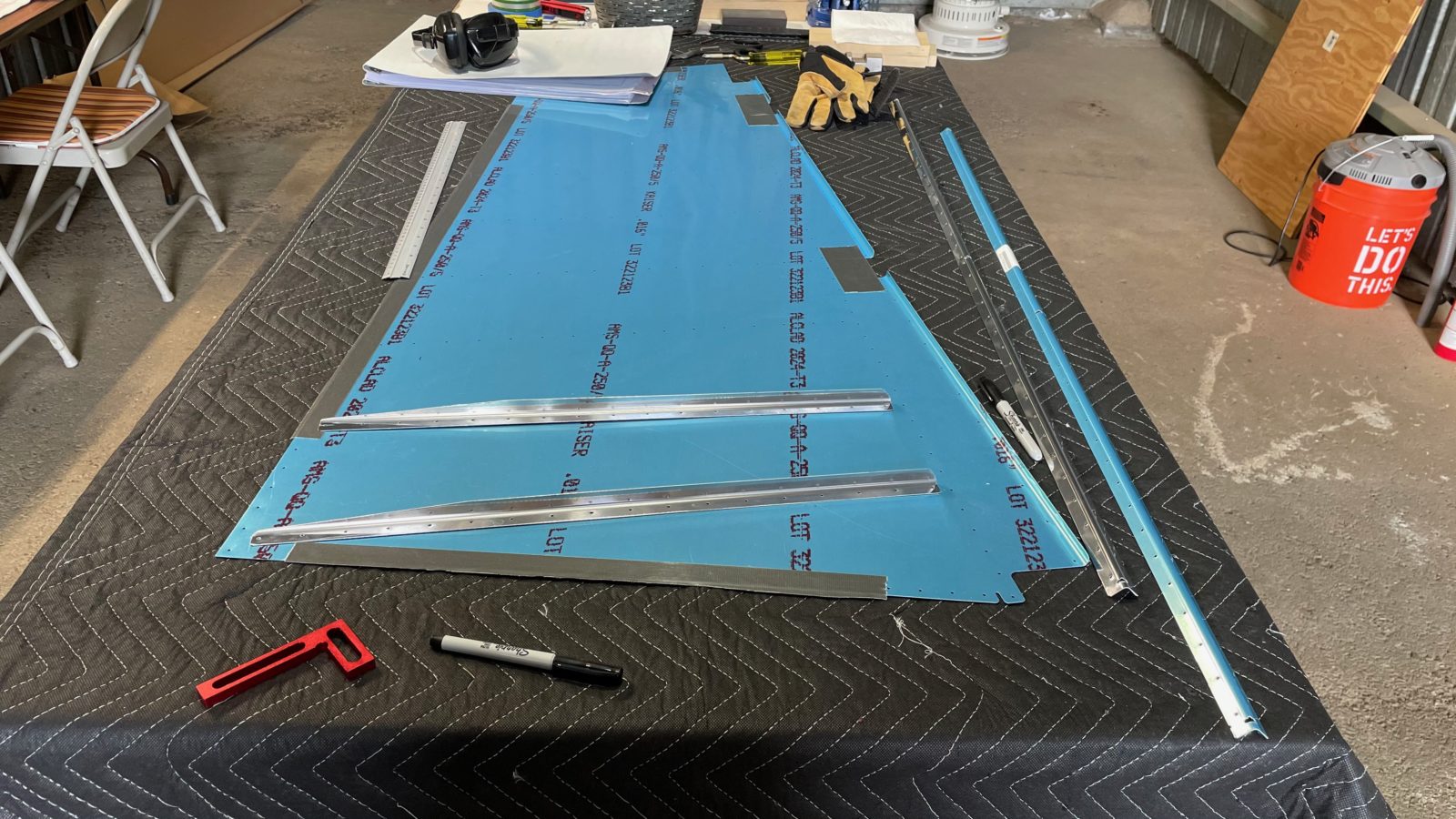
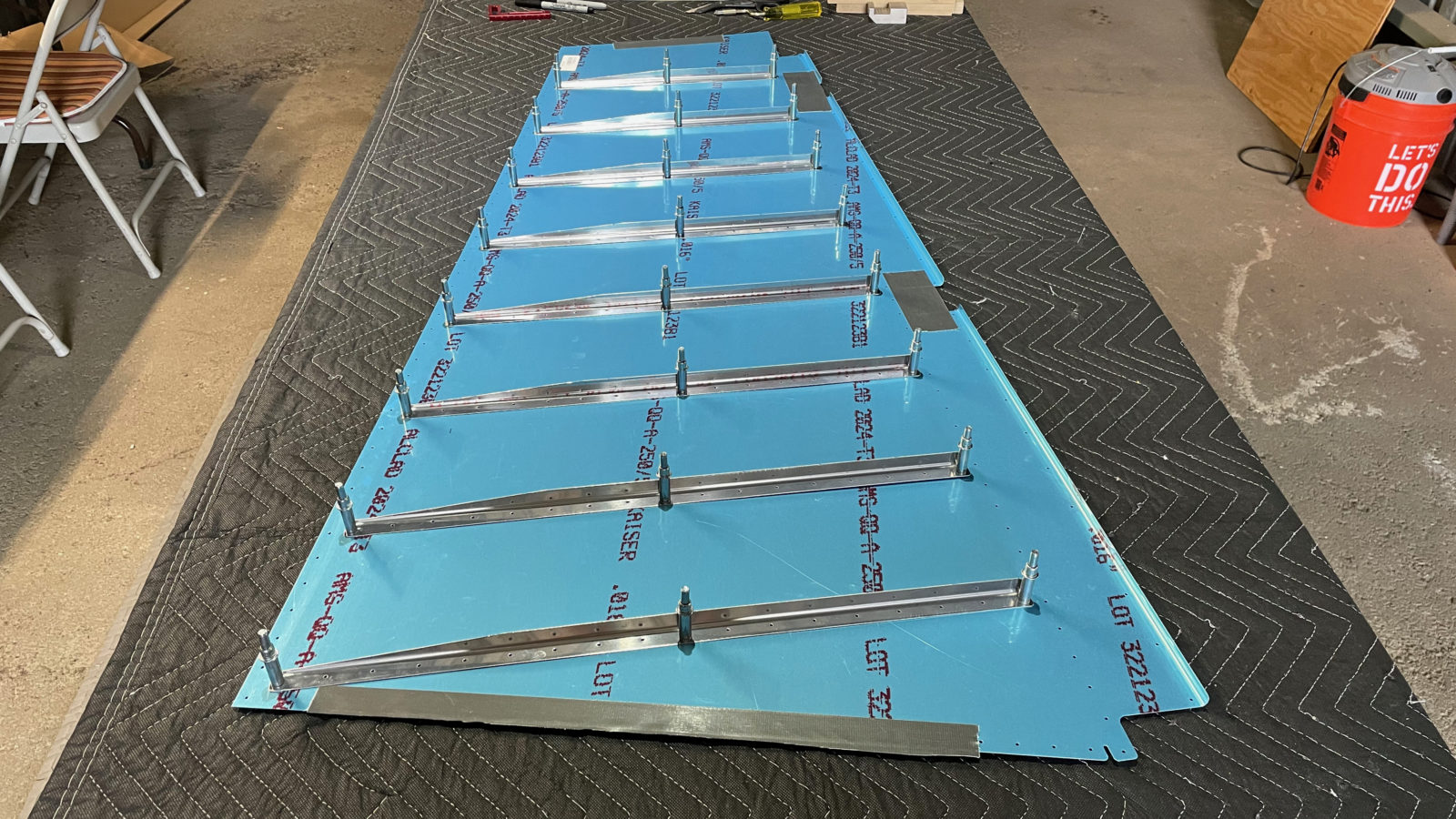
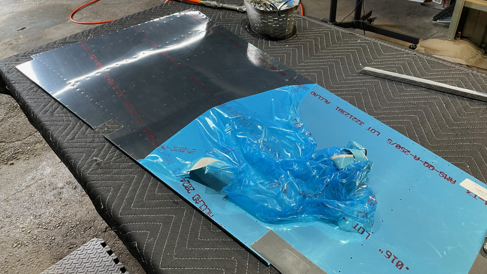
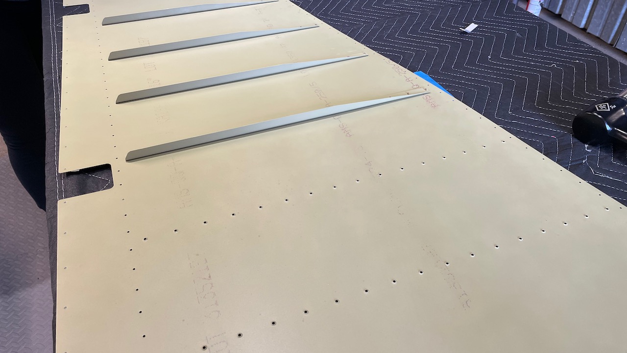
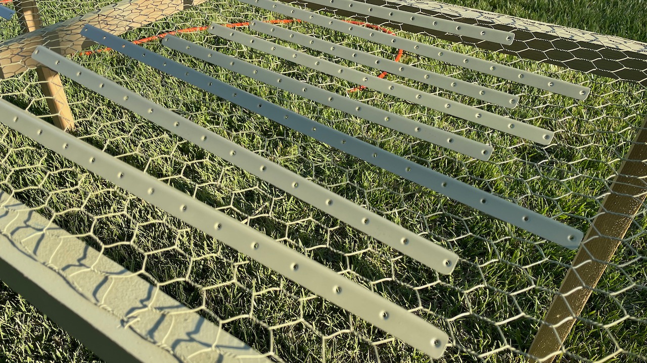
Today we brought back all the rudder parts that we primed in order to start the assembly. There aren’t that many parts in this phase. The biggest ones–the skins–were prepped in an earlier stage and are waiting to be mated to the “skeleton”, which is what we’re working on today
Pieces-parts of the skeleton
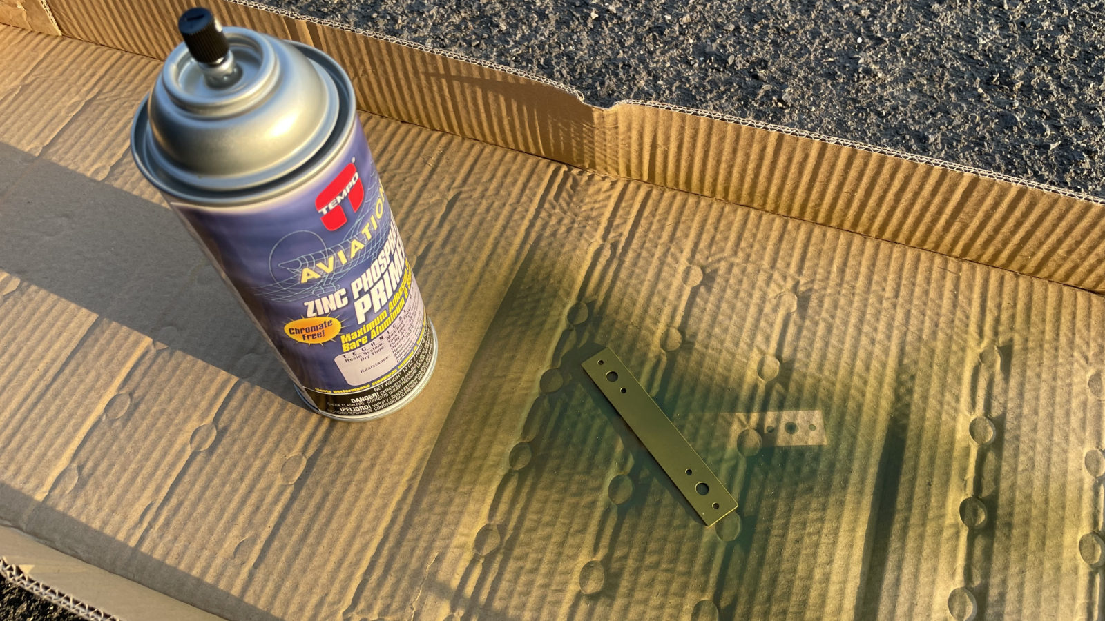
I did not prime one of the parts, a bracket known as R00001, because it was not in the instruction sheet, but instead called out on the plans. That’s why it’s really important to read BOTH the plans and the instructions to make sure you don’t miss anything.
This part was also not where I’d expect it, in a baggy with all the nuts, bolts and other paraphernalia required to assemble. In fact, when I saw it on the plans, I began to manufacture it until Sheila found it in the bag of parts. Fortunately it’s already punched and cut. I just needed to prime it. This was the first test of the primer rattle cans I bought for just such an occasion.
Rattle can FTW
This worked out okay, but remained tacky for a LONG time. With AKZO I can handle the part within 15 minutes (usually dries to the touch in 5). With this stuff, it was tacky an hour later, when I could no longer wait for it to dry. This’ll definitely be a last resort. I *do* have a small paint gun I keep at the hangar. Maybe next time I’ll mix a bit more AKZO and bring it along to touch up anything.
First up was riveting the reinforcement brackets for the vert stab attach points. Easy peasey. Next up was attaching the counterbalance rib, then the counterweight. That was okay as well, however it was there that I noticed I primed both sides of the counterbalance skin, which means there will be one part of the airplane that will be green. :/ I was a bit disappointed, but it’s not the end of the world.
The assembly of the bottom of the spar went okay. However it did take a bit of puzzling to arrange for the riveting order…it’s a complex assembly. I bolo’ed the first rivets in the lower reinforcing plate. Not sure why I was smearing them so badly. I drilled out 2, but kept the center one in place. It doesn’t look that bad, and there are 11 rivets holding that plate in place. One questionable one isn’t going to amount to anything. This is probably what happens when you go a long time without using the rivet gun. I’ve grown soft relying so much on the pneumatic squeezer!
I elected to go with pop rivets for the final connection. It was too weird and awkward trying to get even the smaller bucking back inside the cavity of the horn brace. I technically could have done it, but based on my riveting performance, I figured I’d just botch it up good. So, 4 more LP4-3 rivets were deployed!
All done!
It’s still warm out, so we’re starting work later in the afternoon, with just a 24″ fan to keep the air moving. I may purchase a swamp cooler for next summer so that we can work a little longer. We’ve also started working on Thursdays along with the weekends, as I want to ramp up the number of hours per week we’re working.
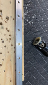
Next up is attaching the skins to the rudder frame and preparing for the critical trailing edge work, which will involve drilling a heavy duty angle iron I picked up from Home Depot, to which I will glue up and cleco the leading edge to. This is done to make the trailing edge as straight as possible. No more than 1/10″ bow permitted across it’s length!
After that comes the leading edges, which we’ll roll with a 1″ wooden dowel and pop rivet. I’ll get to use my new pneumatic pop riveter and edge-forming tool!
While watching some YouTube videos, I noticed some sheet metal tips in the comments that I thought were worth keeping. Here they are:
The only time you use a Vixen file is for heavy shaping.
There is no need to debur your pats before you drill, you will only have to debur it again.
There is no need to ream a hole for a rivet, only when you use a Hi-Lok (close tolerance hole).
When you do use a reamer, once you have taken the hole up to proper size, stop the drill motor and gently pull the reamer out or you will make your hole to big and it will be out of tolerance (close tolerance holes).
When you do get to the point of deburring your parts use a scotch bright disc and a side grinder (much faster).
When you round your corners the radius should be between 1/8 & 1/4 (or .125 & .250), it’s a stress thing when the metal parts come together. the sharper the point, the more the possibility for stress at the point. You can also make it a 45º chamfer, but I prefer a radius.
Another great tip from Guil was that for machine countersinking, cut to hold a rivet flush, then 7 clicks (.007″) more to accommodate the dimpled piece that will eventually sit inside it.
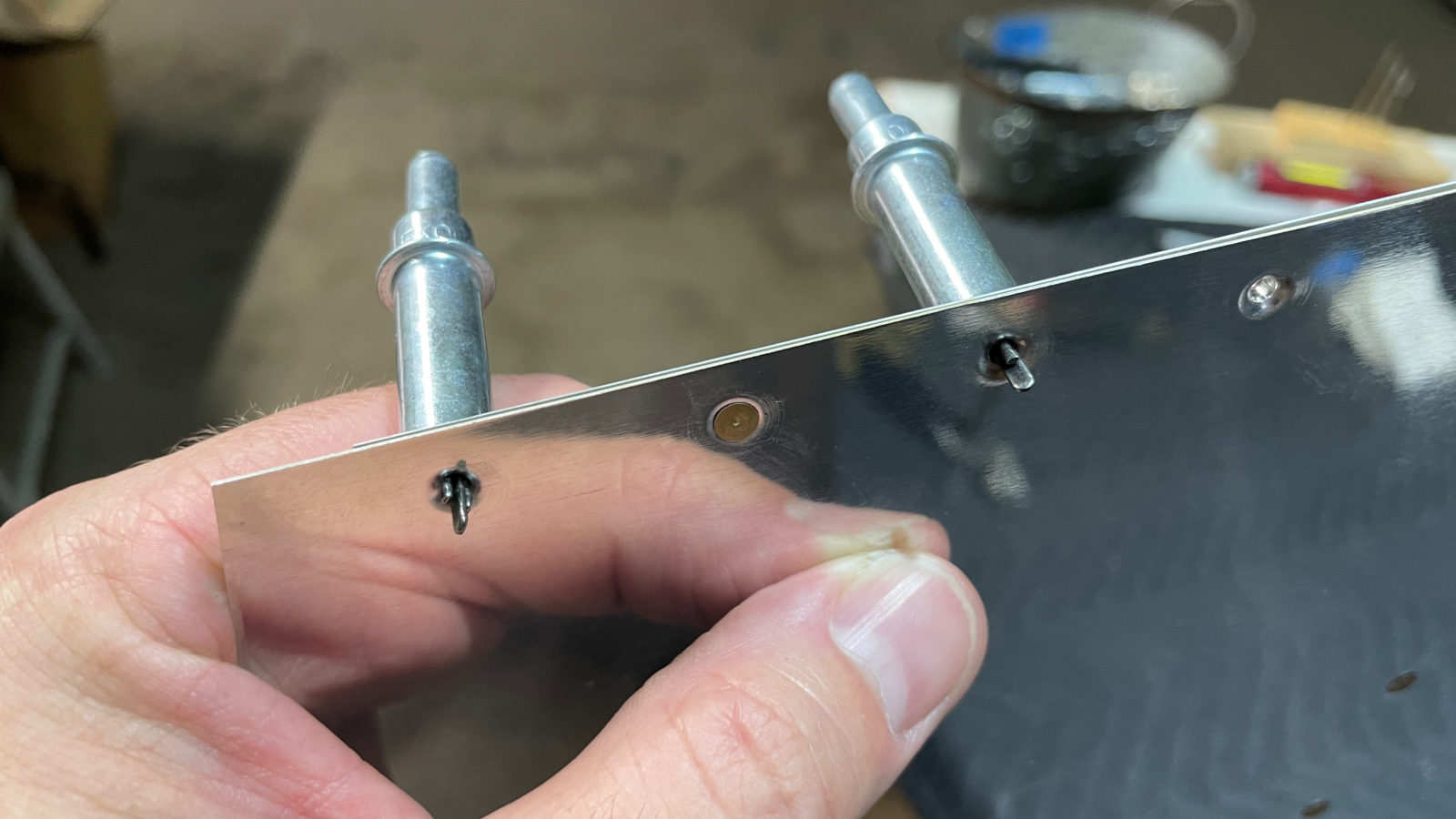
So we’ve taken a bit of break, but we’re back at it! Today we continued working on prepping the rudder for assembly. I had to wait for a #10 dimple die set I bought from Cleaveland Aircraft in order to make 2 dimples in the counterweight rib. I hope I get to make more #10 dimples…these die sets ain’t cheap! 😛
Dimples produced!
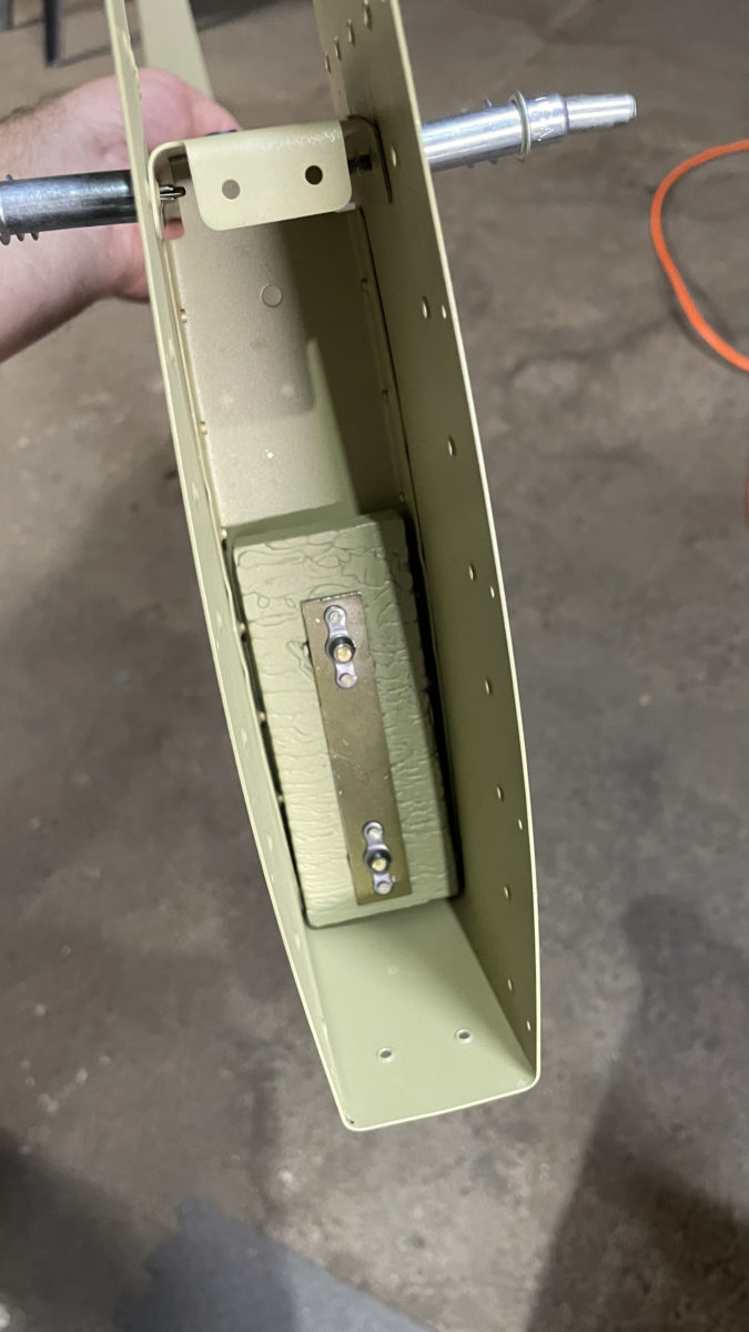
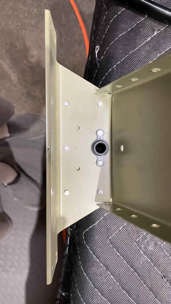
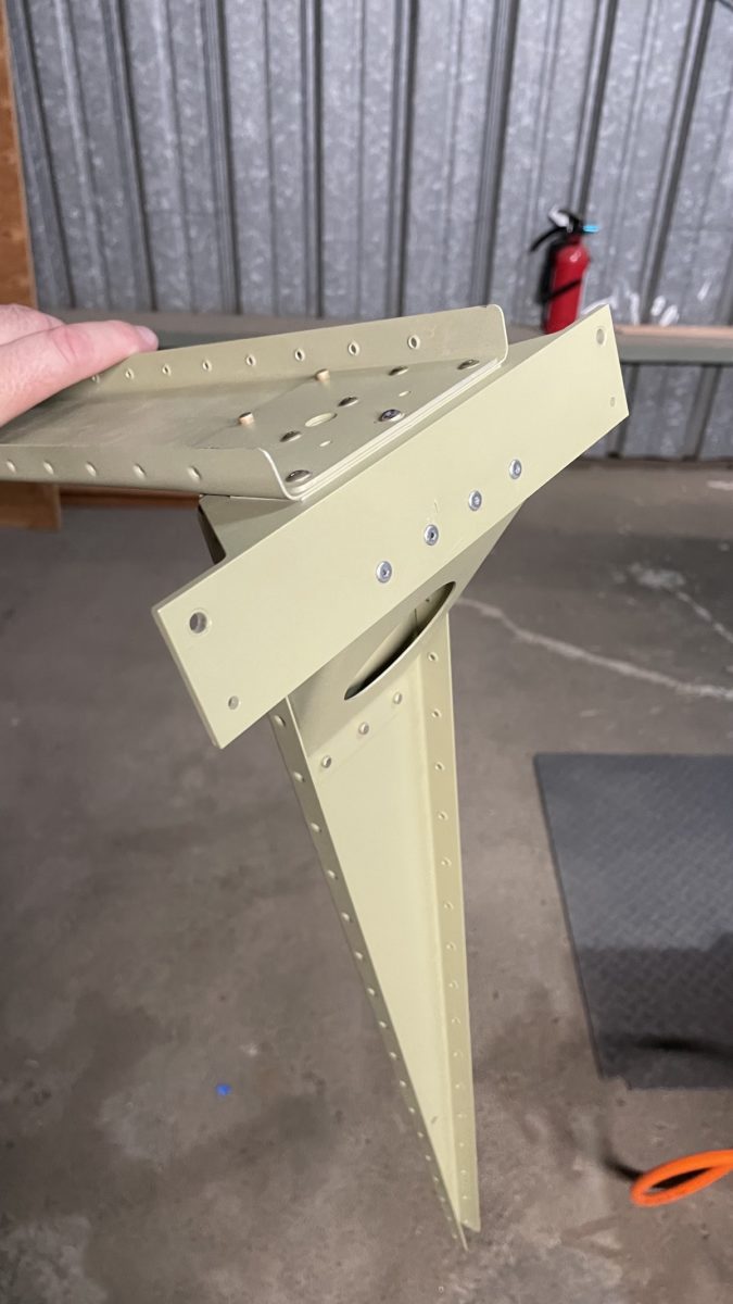
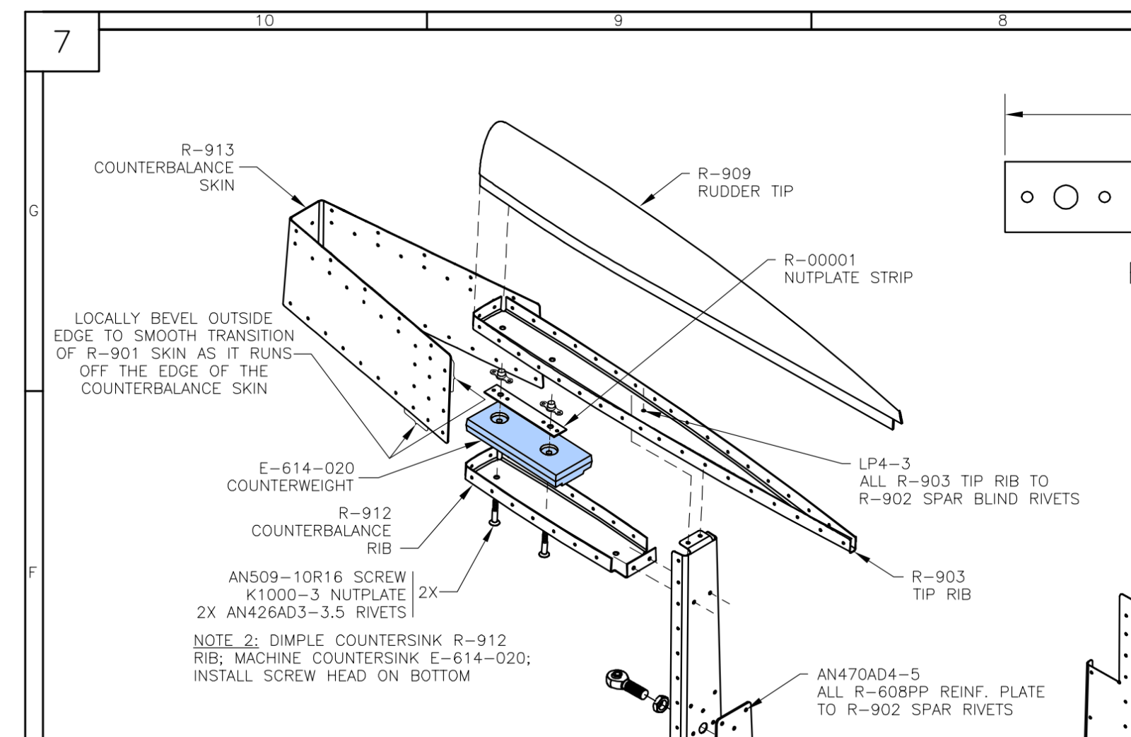
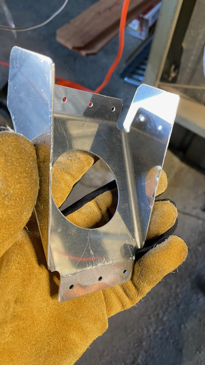
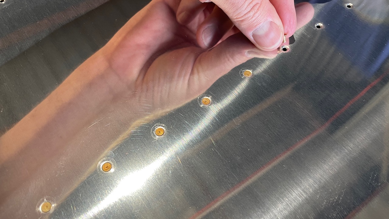
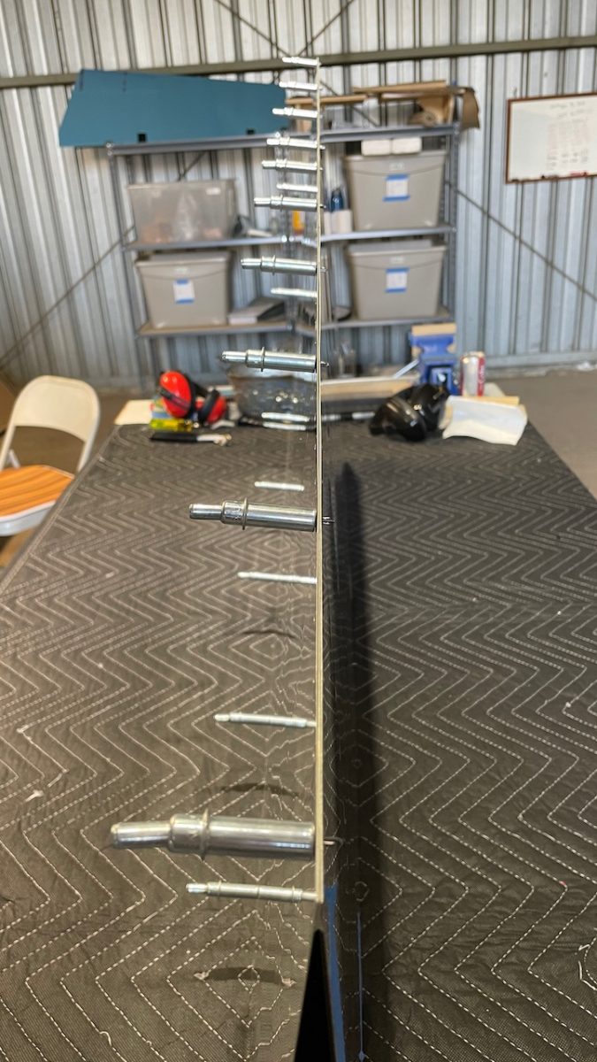
Once the dimples were in, it was time to machine countersink the lead counterweight. As it turns out, I did have the #10 countersink cutter! Fortuitous me! These parts are located at the top tip of the rudder, and I believe the weight helps with preventing flutter in the rudder while flying, which unchecked could lead to a dangerous condition.
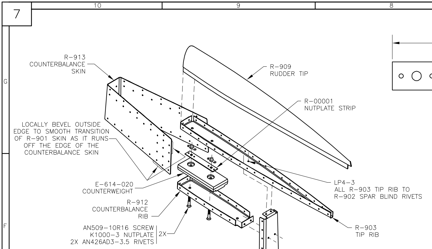
Location of the rudder counterweight
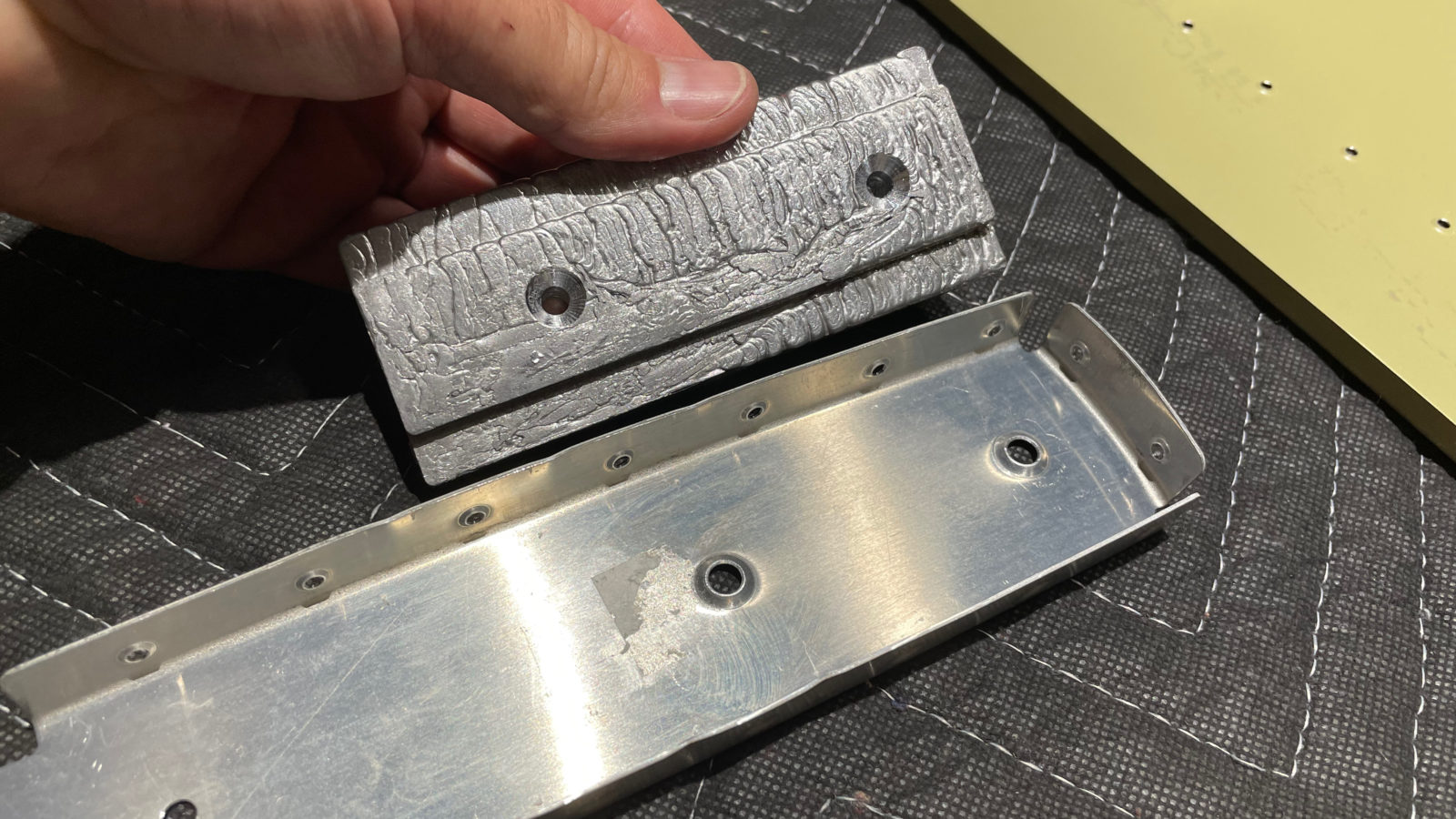
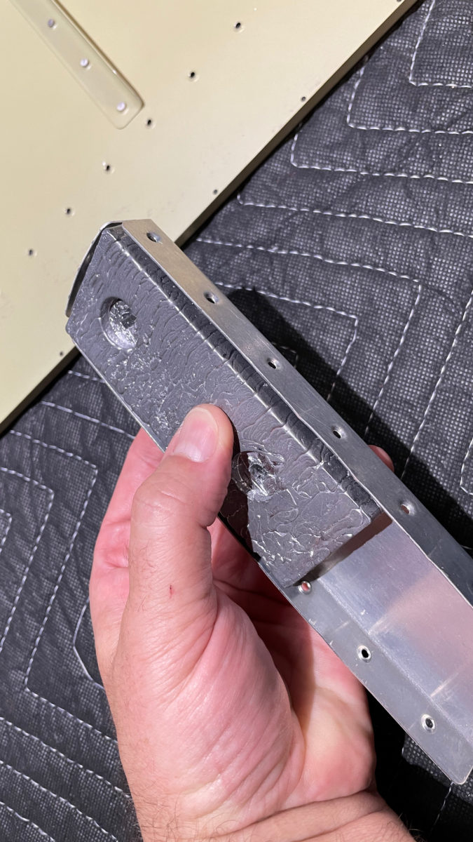
The other thing I worked on was machine countersinking the through holes in the trailing edge wedge. This aluminum wedge is what joins the aft rudder skins together. Since the skins are dimpled, the wedge needs to receive countersinking for the holes so that the skins nest snugly against it with no gaps.
The infamous Edge Wedge
In the above pictures, starting from the left, I’m doing the machine counterskinking using a special countersinking drill attachment. In the middle and right pics, I’ve finished all those damned countersunk holes and I’m testing the fit. No gaps! This part wasn’t as bad as I thought. When riveting the trailing edge, I’ll be using a technique called double-blind riveting, where the rivets are back-riveted while progressively tilting the rivet gun to semi-smoosh the shop end of the rivet so that it sits flush. It doesn’t completely fill the rivet dimple, but looks pretty nice if you do it right. I demonstrated this early in the blog when we worked on the flap kit.
Here are a couple other pics from this short work night (just 2 hours). Next up is priming, then we start assembling the rudder!
Wing kit update: Looks like the wings are delayed a bit in shipping. They should be here soon though!
Tonight we’re back at it, working on finishing up the rudder. We’re at the point now, with the skins finished and primed, where we connect up everything and check for fit, then match-drill all the holes, deburr and dimple, then bring the remaining pieces home for priming. Total time tonight: 6 hours.
We ran into a couple small issues, which I’ll either ask the community or Van’s about. Here’s the entry from our EAA builder’s log:
Resumed work on building out the rudder. Work included assembling the rudder, match-drilling, deburring, dimpling ribs and spar. Issues: nothing in instructions about drilling the R-710 rudder horn brace, but it seemed like this was the time to do it. Notch in skin was misaligned with R-405PD rudder horn on 1 side. Will probably widen the slot in R-901 skin to accomodate. Lastly, looking for guidance on drilling/dimpling the top row of holes on the R-913 counterbalance skin. Instructions just say to match drill, deburr and dimple the 913-to-901 holes. Looking ahead, the attachment of the rudder tip, R-909, will use similar process to detail B-B on drawing 6, but I can’t find the instructions on when to accomplish that. Seems appropriate to do so before priming.
https://eaabuilderslog.org/?s=mcarter
I think I’ll probably just widen the slot in the skin so that it doesn’t stress so much…
It’s only happening on 1 side, but it’s kind of weird. That’s a fairly good-sized misalignment.
The other thing was that there was no indication in the instructions that we needed to drill through the R-710 horn brace while match-drilling the skin to the spar. It may have just been inferred from the other work, but I think the instructions mentioned all other pieces _but_ the brace…
Trim the excess material from R-710 rudder brace. Fit the R-710 between R-405PD and R-904. Cleco the aft edge of R-710 to the bottom of R-904 and drill #30. Match drill through the forward edge of R-710 using the holes in R-405PD as a drill guide.
– From the manual.
This is the only place in this set of steps that the R-710 is mentioned, and the match drilling is only for the three holes between the brace and the inside of the spar, not the flanges of the spar to which the skins are attached.
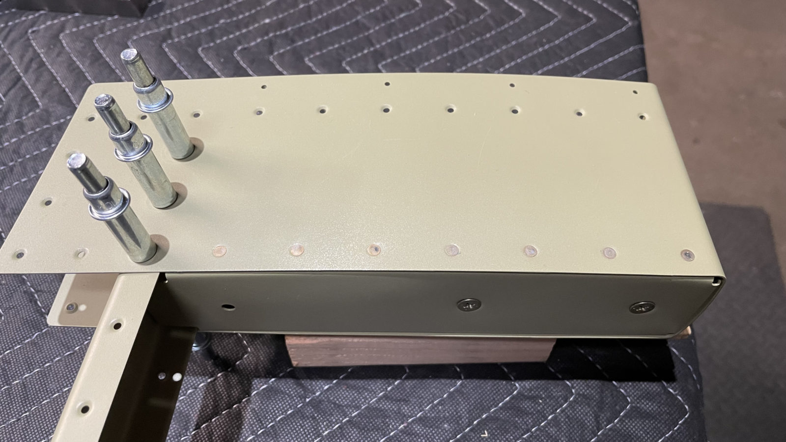
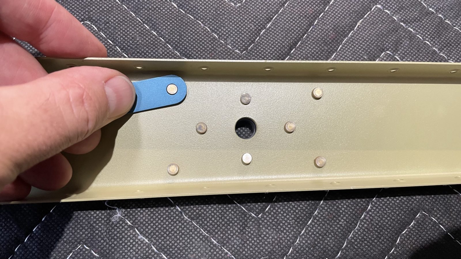
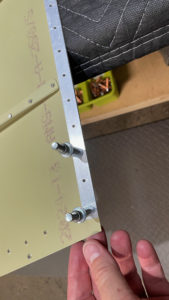
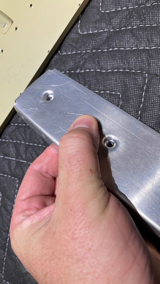
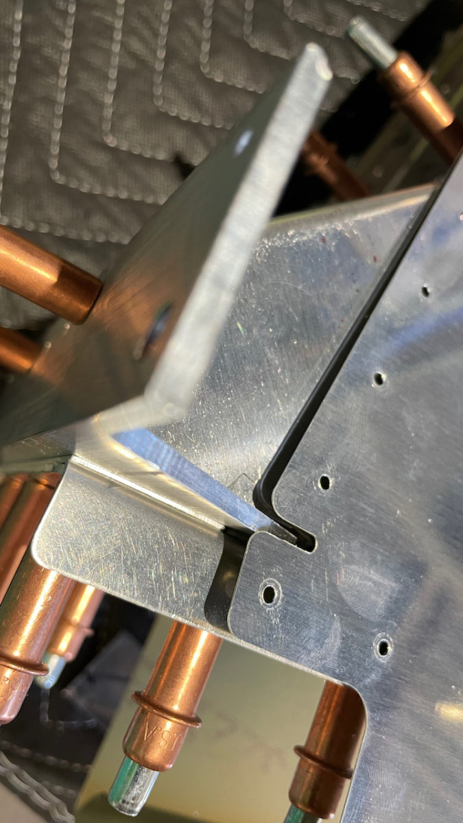
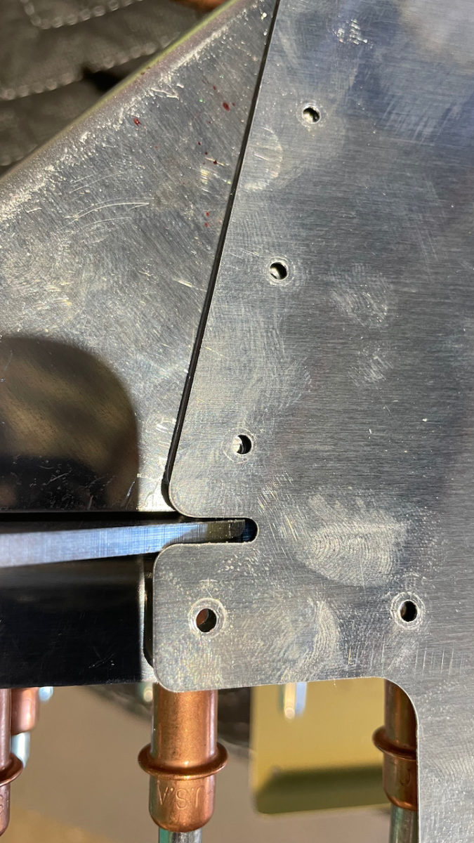
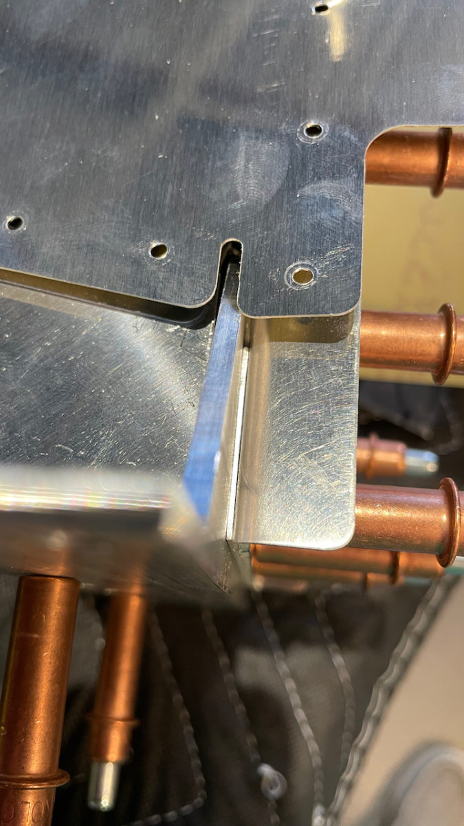
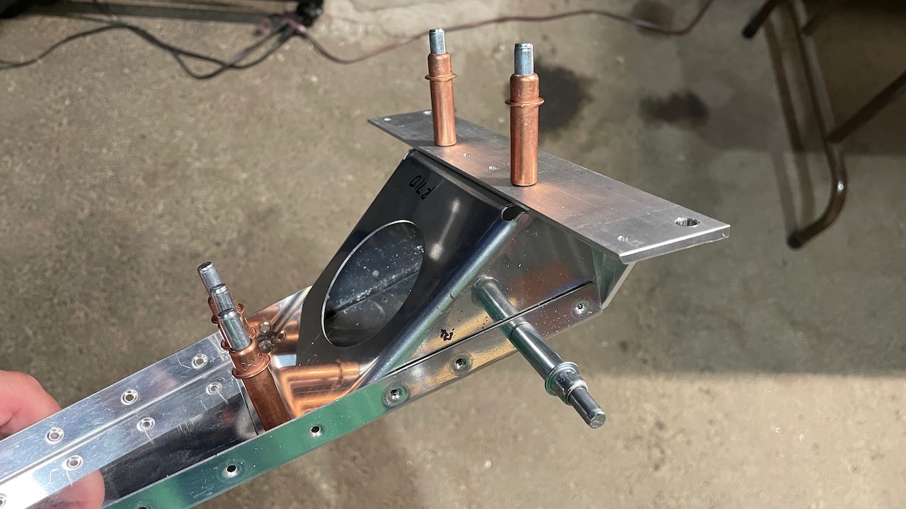
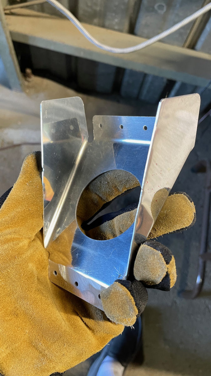
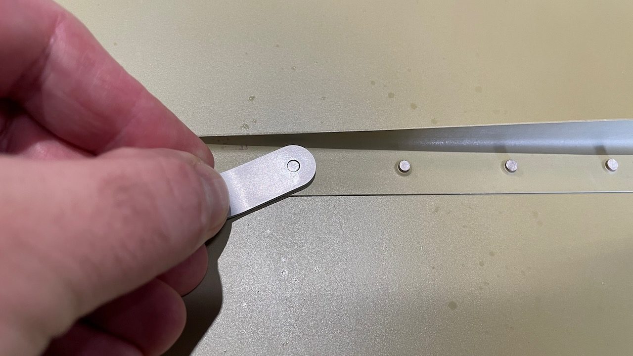
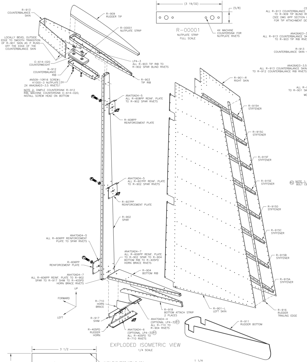
Horn brace 710 is the part on the right side under the skin, with the 30° angle moving down
As you can see here, there are 4 holes where the horn brace sits behind. You obviously can’t rivet the skin to the spar if there aren’t holes and dimples in the brace! So I went ahead and drilled and dimpled the sides of the horn brace so that they can all be reveted together.
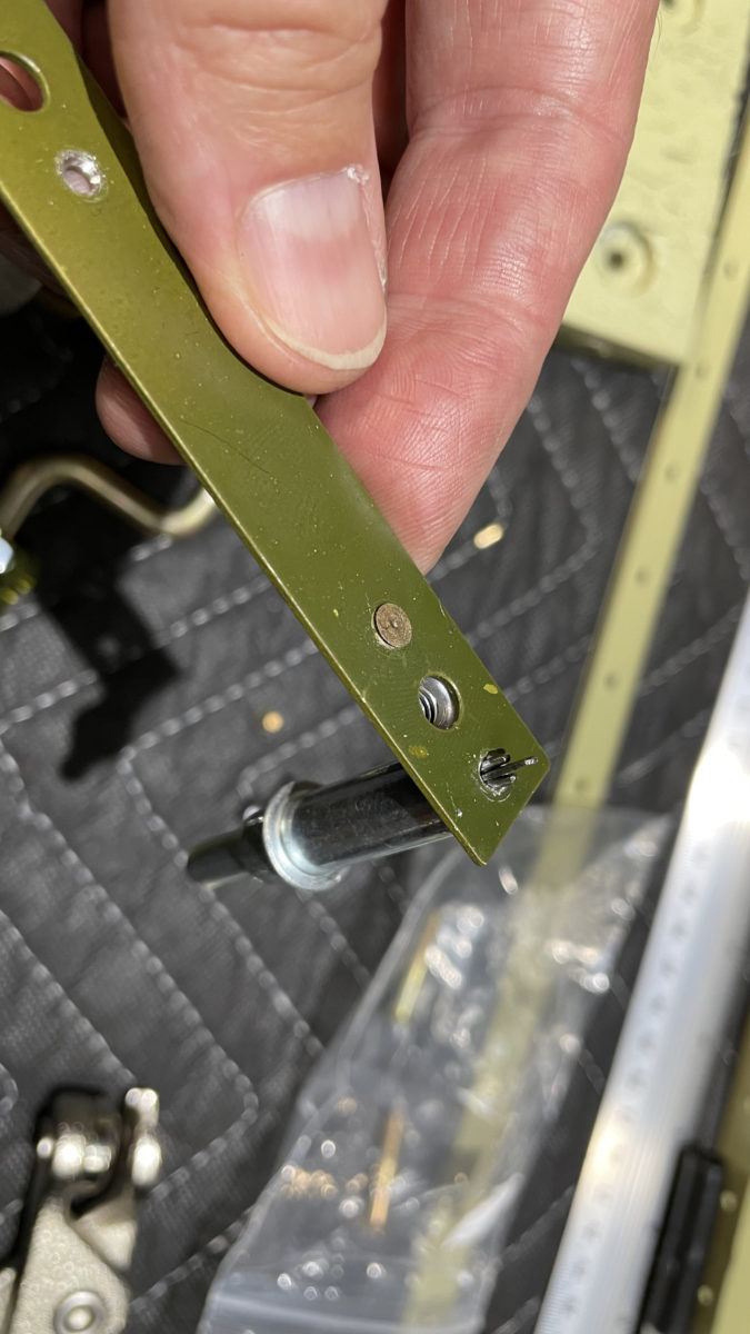
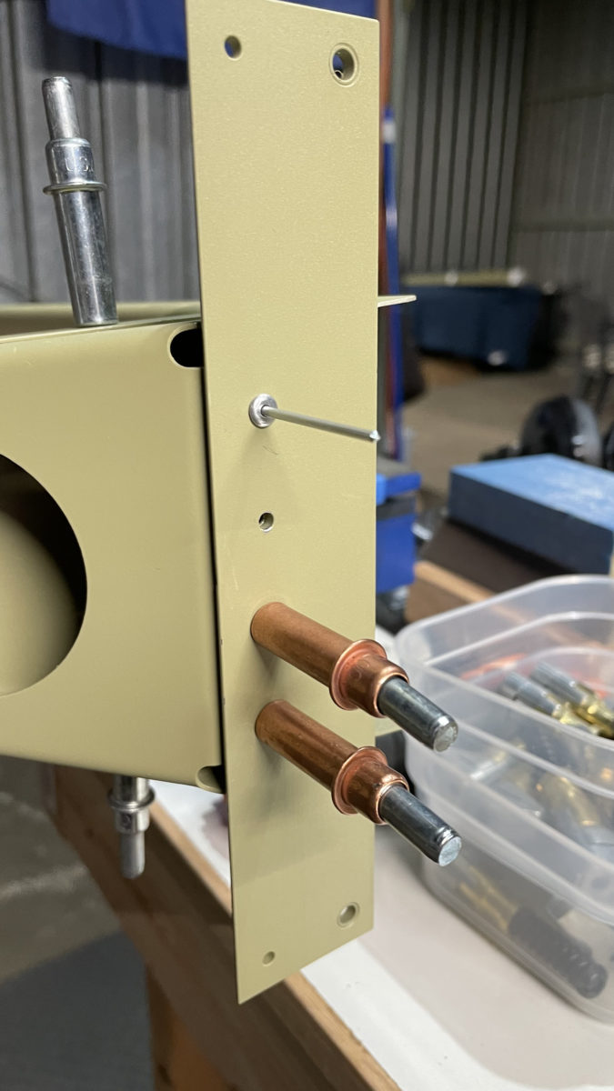
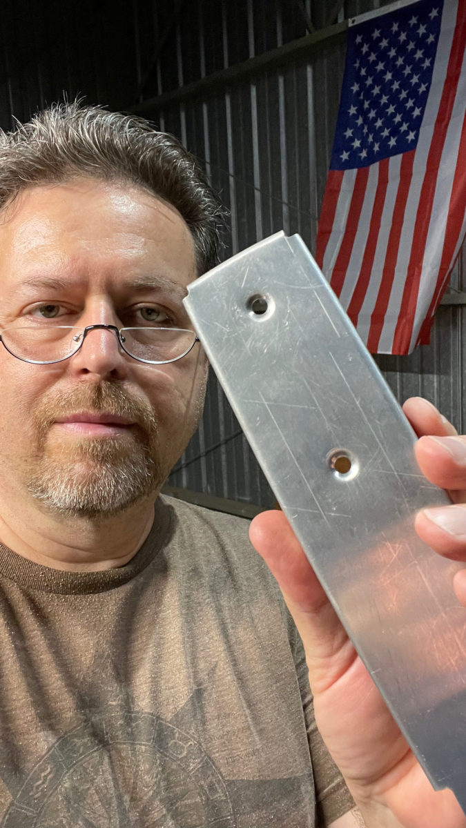
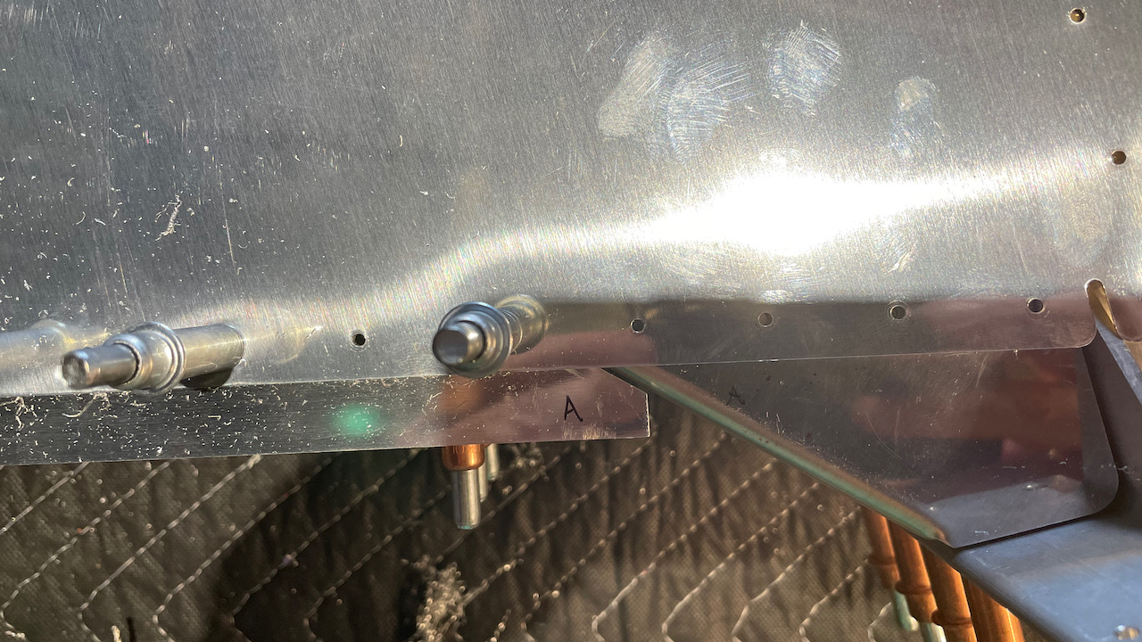
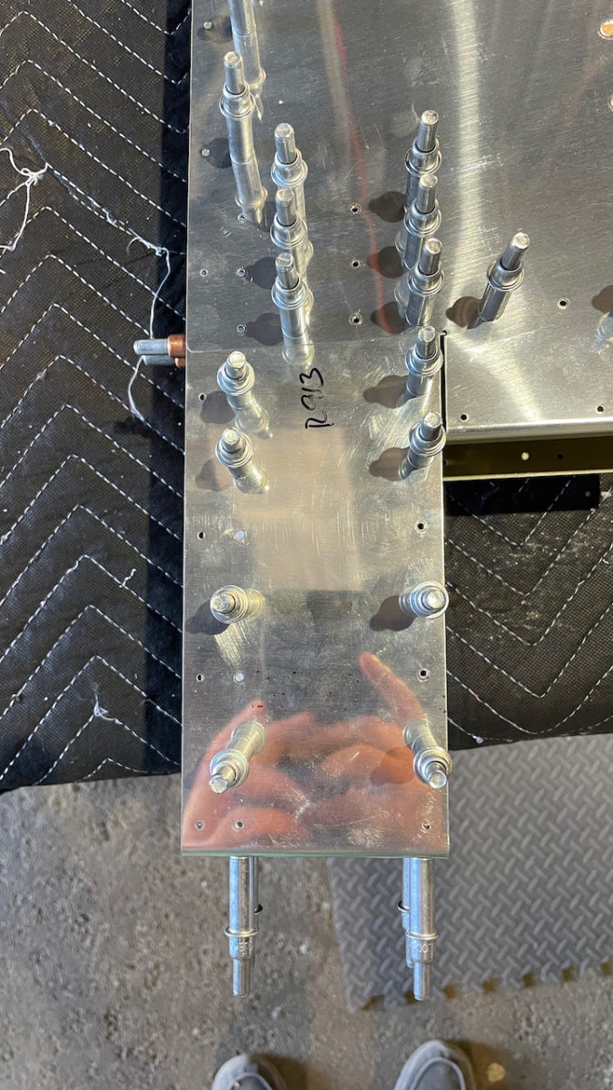
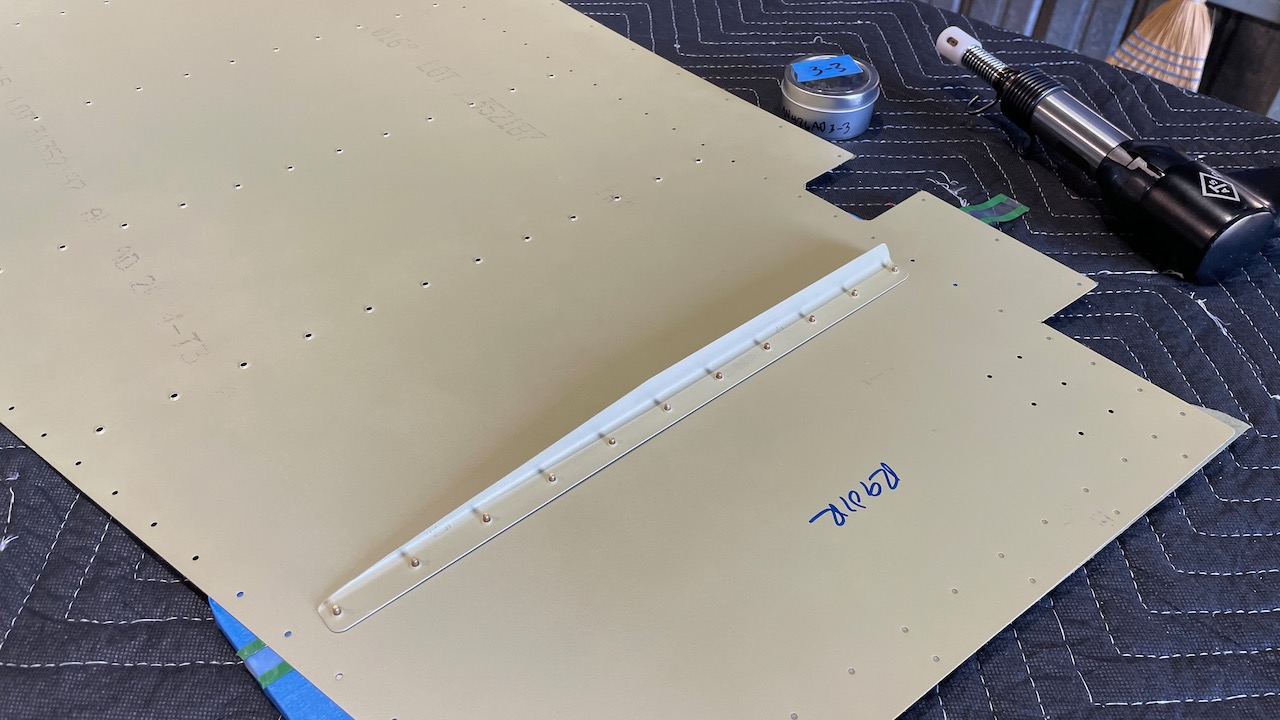
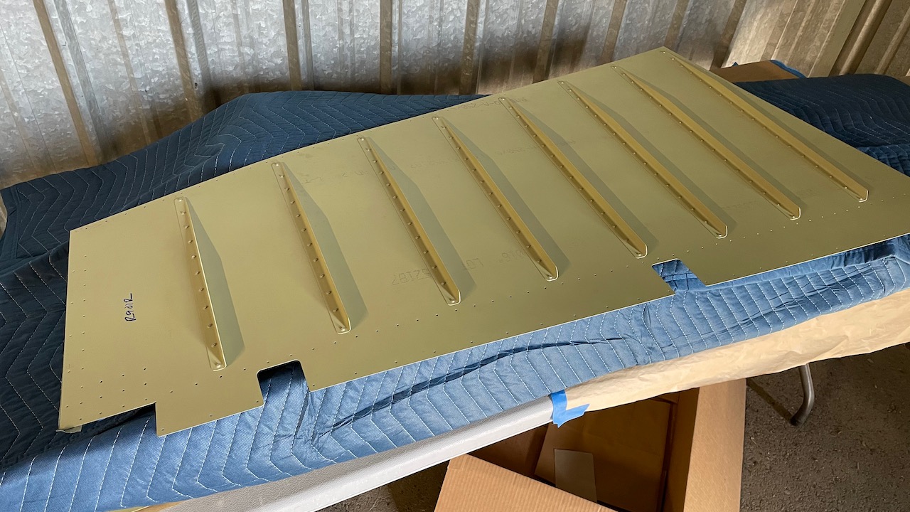
Lastly is the counterbalance skin, which sits at the top of the rudder, atop the skins…
The dastardly counterbalance skin
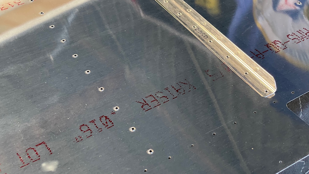
Here, we’re told in the instructions to match drill, deburr and dimple all the holes in the counterbalance skin where it meets the main skins (R-901s), along with the ribs and spar. That doesn’t include the top 10 holes (5 each side), which will be used to secure the rudder tip.
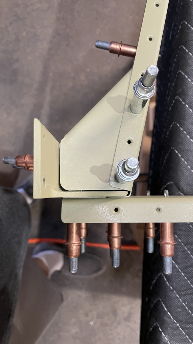
First off, this was a pain to attach to the ribs! it’s fairly thick, and there is a sligh bow in the end, which matches a slight bow in the ribs. You can see the bow in R-903 and R-912, where it attaches to the counterbalance skin. The first time I tried to cleco everything together, it wouldn’t work. Tonight, it worked. Weird. I did use a small awl to help “fold” the skin over the ribs and get the holes aligned. Good, tight fit, that’s for sure.
So what to do with the 5 holes along the top edge? There is no guidance in this section on what to do specifically. I think it’d be easy to go ahead and assume you have to match drill, deburr and dimple them along with the rest..which are all #40…but that’d be wrong. Here’s what the instructions say:
Cleco the R-913 counterbalance skin to the R-903 tip rib and R-912 counterbalance rib. Match drill #40 the counterbalance skin to the ribs using the pre-punched holes in the R-913 counterbalance skin as a drill guide.
– From the manual.
The issue is, if you look ahead to see just how the R-909 rudder tip attaches to the counterbalance skin, it uses a larger hole and dimple! The instructions don’t directly mention that, although the plans do plainly show a CS4-4 is required. It does say to match drill the skin to the ribs only. A few steps later it say, “Disassemble the rudder and deburr all the holes. Dimple the skin, spar and ribs.”
Technically, the counterbalance skin is a skin. If you were to go ahead and dimple all the holes, that would include those top 10 holes. However, that’d cause an issue later when it becomes evident that you need to use a CS4-4 rivet for the attachment of the tip, which requires a #30 hole. If you had already drilled/dimpled the hole for #40, you’ll need to rework it later, which could weaken the aluminum. So I’m thinking we should probably drill those top holes in both the 913 and 901 skins to #30 now instead of later. Weird how the holes are pre-drilled for #40 tho. I think I’ll bring this up to Vans.
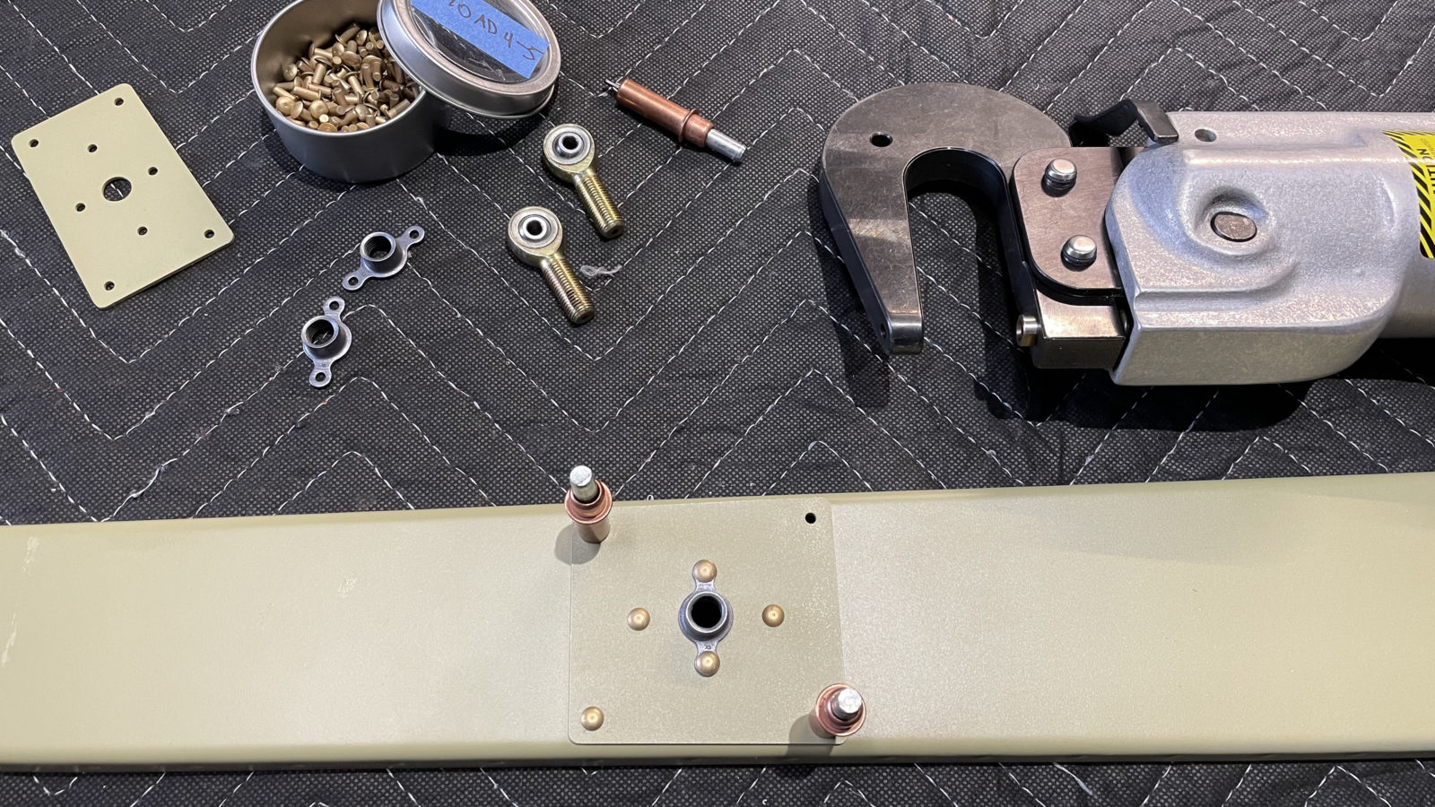
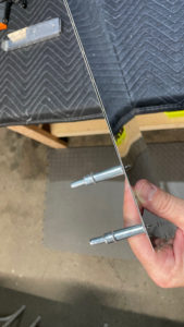
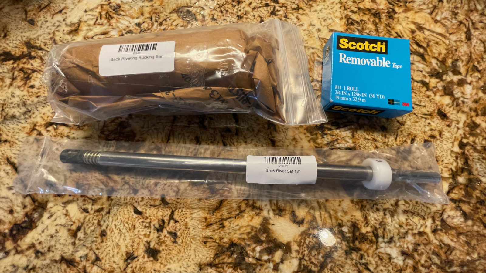
While we wait the 6-8 weeks for the wing kit to arrive, I’m trying to make sure we have all the tooling we’ll need, in advance. In this order, a longer back rivet set, and a hand-held back-rivet plate!
I watched a video where the builder back-riveted the wing skins on in order to get a smoother finish, especially across the top of the wings. What a great idea! I asked him where he got his hand-held back-rivet bucking bar, and he mentioned Cleaveland Tools. They usually have very good quality stuff, and no exception this time!
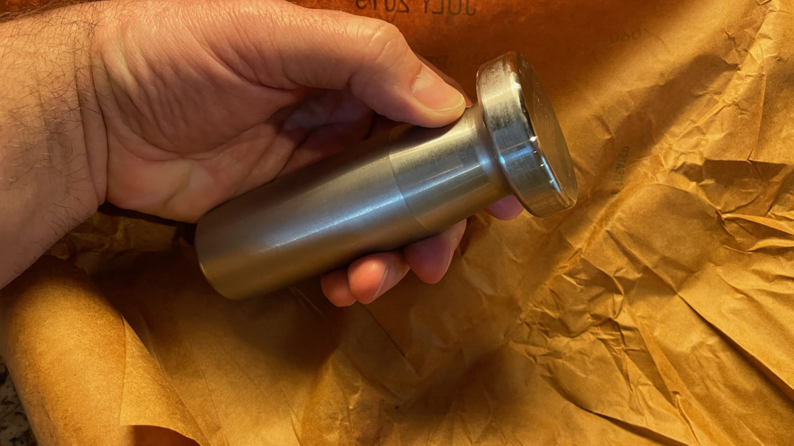
The bucking bar is wrapped in special oil-impregnated paper in order to slow any corrosion. Here’s what it looks like out of it’s wrapper:
For now, it’s back to finishing up the rudder and elevators. I don’t think we’ll have them completed by the time the wing kit arrives, but we’re going to try!
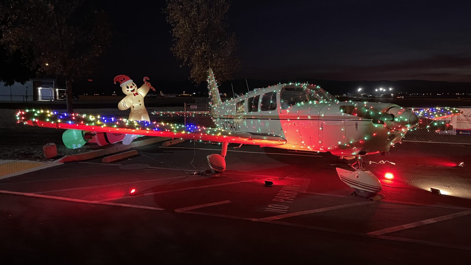
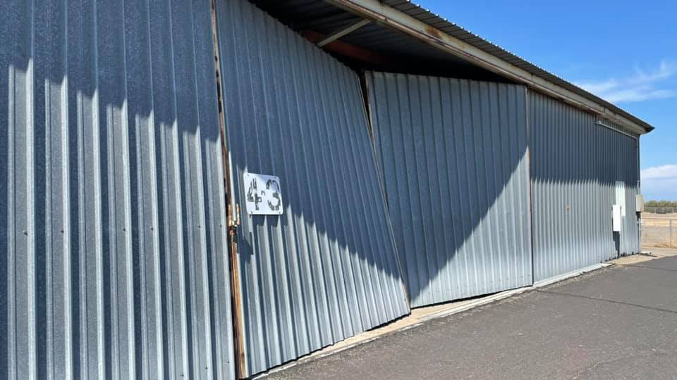
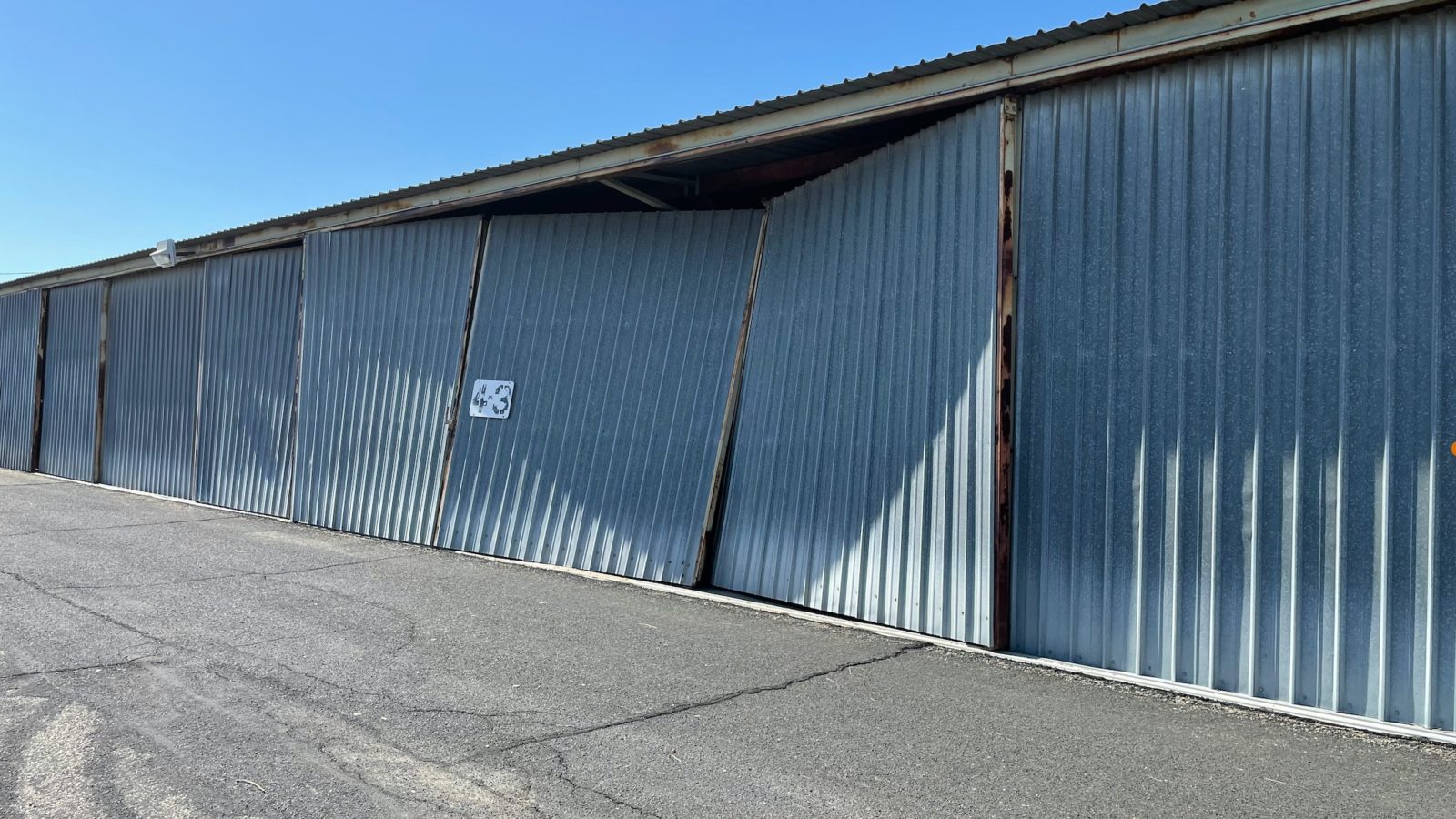
We stopped by last weekend to do some work, and this is what we found! Evidentally it was a tad windy the night before, and it looks like the roof lifted just enough for the door brackets to come free from the tracks!
Fortunately, our doors had very minor damage compared to this. Right behind these doors is a nice Cessna 172H. I was able to peek in and saw that the doors did not contact the propeller or other parts of the airplane. If it had, it could have caused significant damage.
I notified the airport manager and she dispatched a couple workers to check it out. By the next day, the doors were fixed.
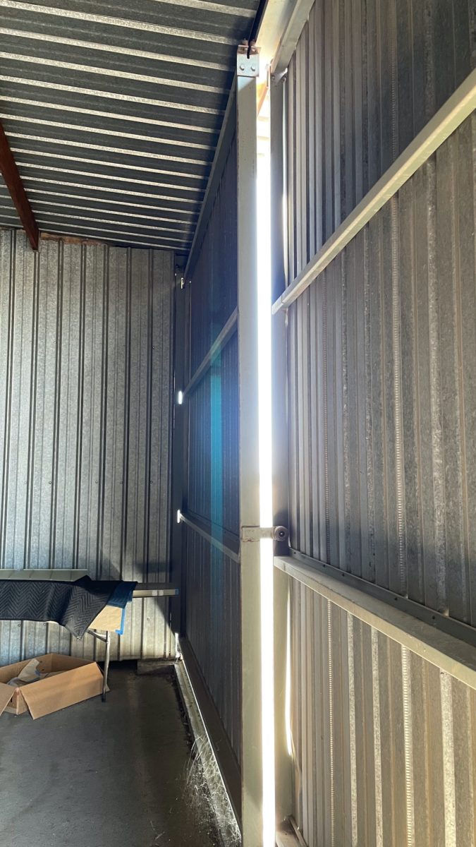
More damage pics
Our hangar is just to the left of this one. The right picture shows one of our doors. The bracket did come off the track, but it didn’t move much.
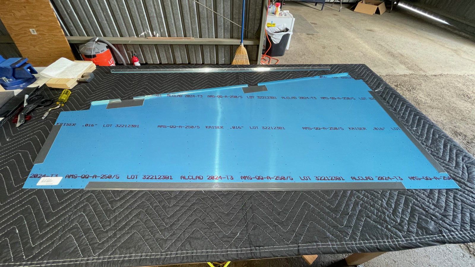
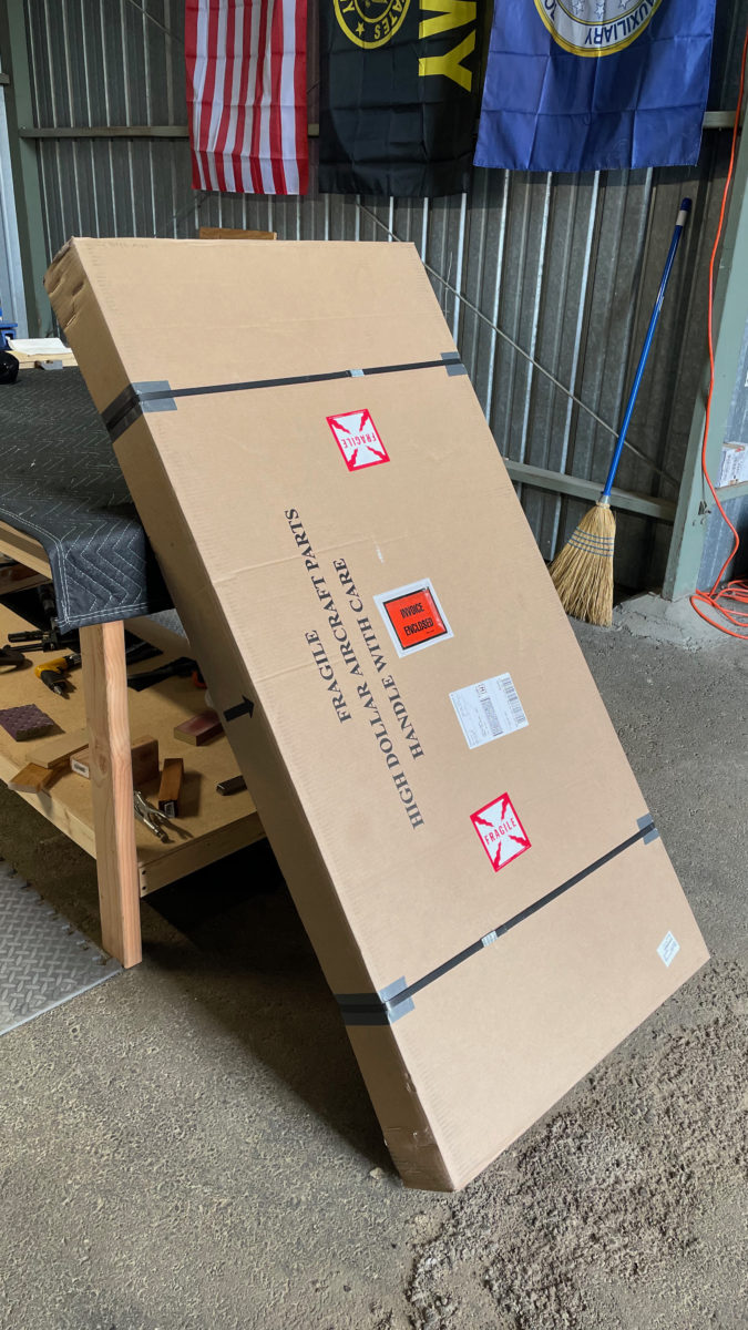
After thinking about the mess I made of the left rudder skin, I decided to just buy another one and give it another shot. The skin itself was only $43 and change. I also needed 8 stiffeners at $5.09 per 2.
Well-packaged delivery
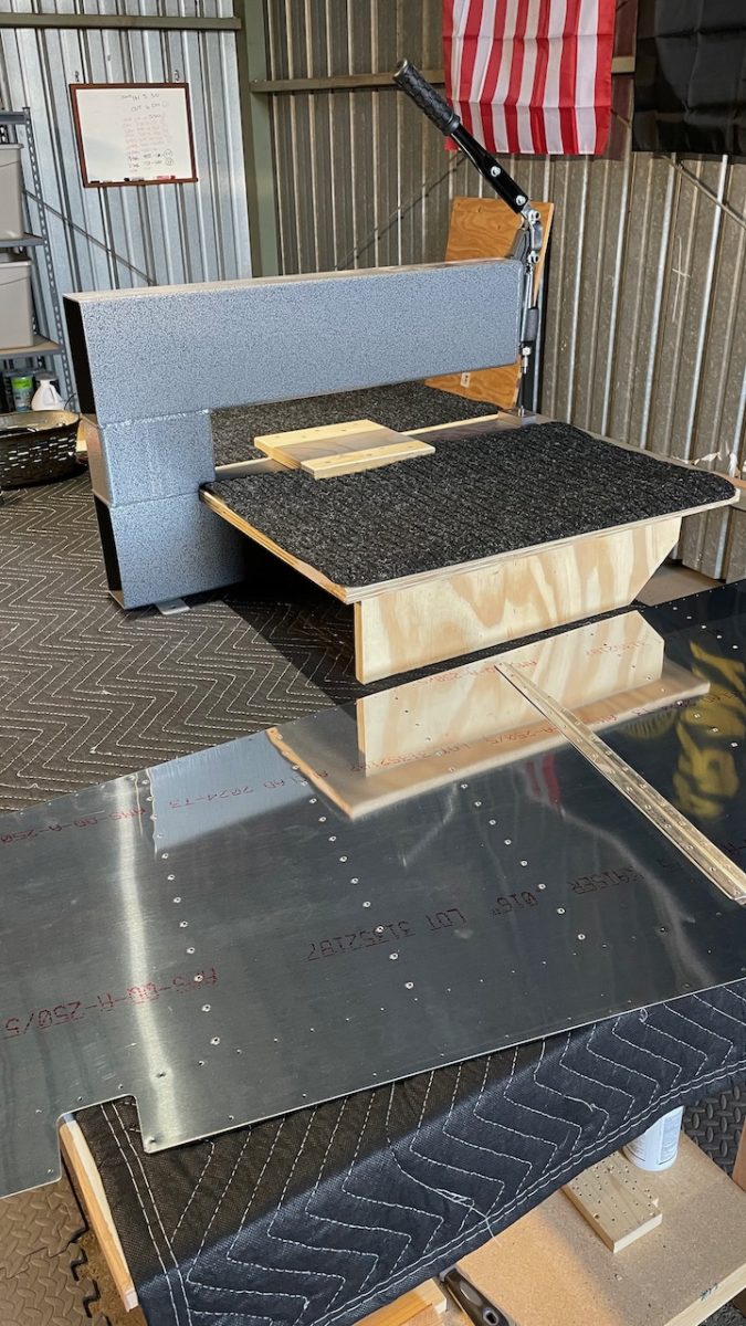
By this point, I’ve gotten good at preparing rudder skins, so I starting Saturday afternoon and finishing with the prep work in 3.5 hours. That included cutting and forming the stiffeners, match-drilling them and the skin, deburring it all and dimpling both the skin and stiffeners. Next is painting…again.
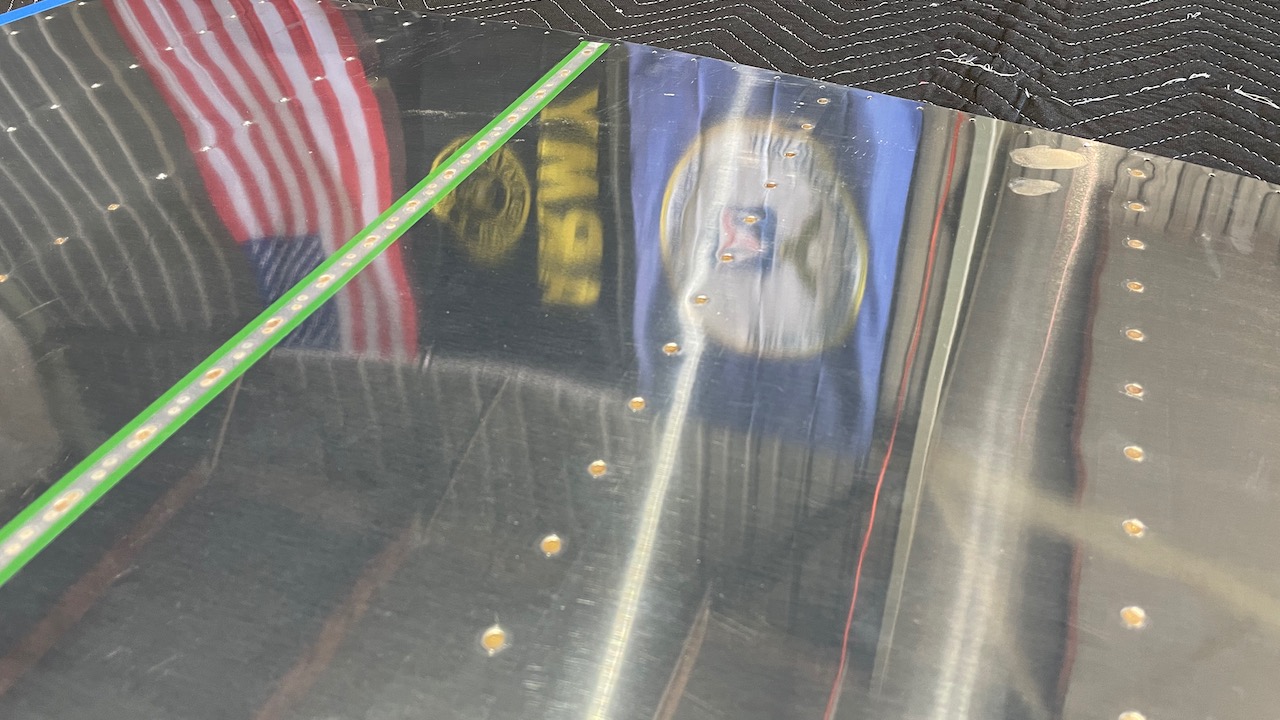
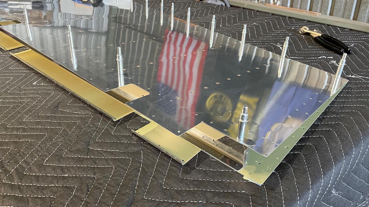
Today we planned to rivet in the stiffeners on the rudder skins, then start the assembly of the rudder skeleton. We used the back-rivet set to attach them. This involves placing a line of rivets and holding them in place with a special tape, which is sticky only on the outer edges. Then a heavy metal plate is placed under the skin, and a special back rivet set is attached to the rivet gun. You then set the rivets from the back side of the work piece. The metal plate is your bucking bar. Generally, the results are very smooth and neat. Generally….
Green rivet tape holding down the next line of rivets to set.
In my case, I messed up what would have otherwise been a perfect skin. We gauge each rivet after a row is set to make sure they got set correctly, e.g. within tolerance according to the gauge. If one is under-driven, a couple more taps with the rivet gun brings it in fine.
The ONE THING you have to be careful about while back riveting is that you MAKE ABSOLUTELY CERTAIN that the back rivet plate is under the rivet you’re about to bash. Our back rivet plate is not long enough to cover all the rivets, especially on the longer stiffeners. I managed to get through the first skin perfectly before I bozoed a rivet on the second skin. 🙁
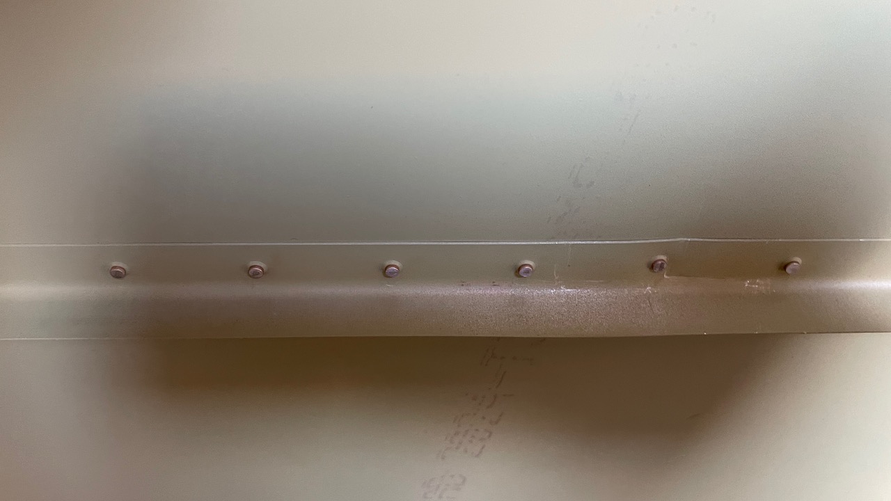
As we were checking the rivets on one line, one was a little under-set. This time, however, I did NOT check that the rivet plate was under this one and banged away. Result? Nothing below the rivet to buck it, and so the skin collapsed under the pressure of the rivet gun:
Mangled rivet. Mike’s a bozoEven bent the stiffener
Overall it’s not a deal-breaker for the skin, but it really hurts when I look at it. It’s definitely going to be visible on the rudder. Paint will hide it somewhat, but I’LL know it’s there. :/
Oh well. Shit happens. Aggravating, tho.
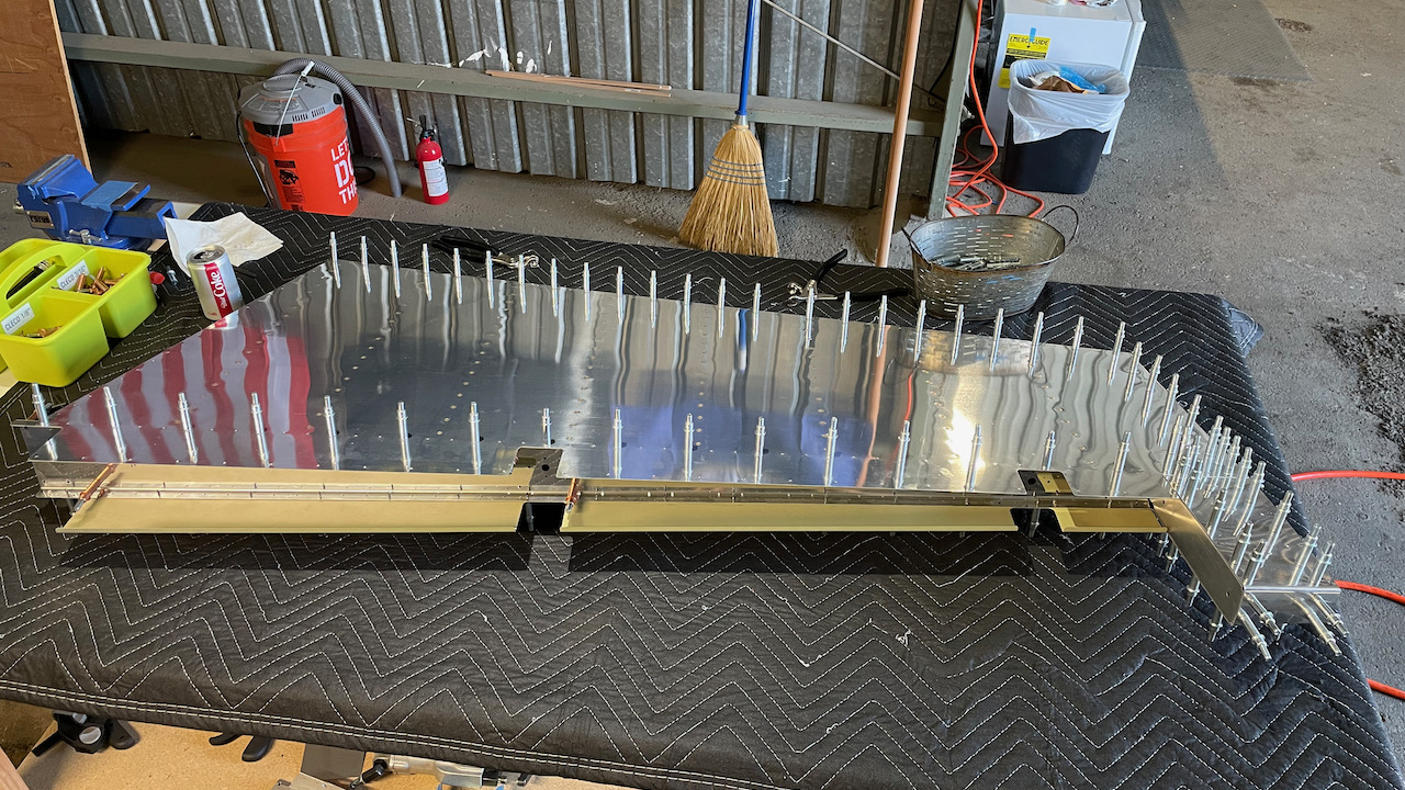
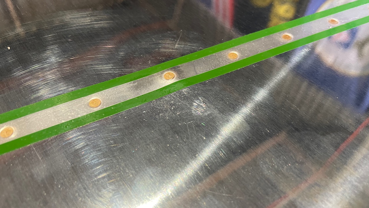
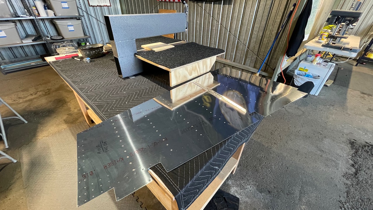
Moving along, I did a test fit of the skins so that I could verify that we cut the stiffeners properly so that they didn’t interfere with the trailing edge coming together in a straight line. We cleco’ed the skins and the trailing edge to make sure there were no bumps or alignment issues. As it turns out, it looked great!
That trailing edge line is a thing of beauty!
We were going to continue on with the assembly of the skeleton, but I needed to go get a 3/8″ drill bit to enlarge a hole, so we called it a day. Total time: 2 hours.
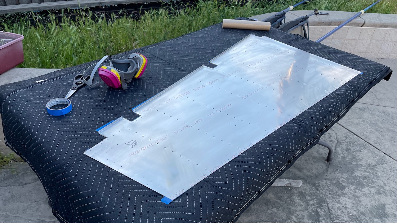
This last weekend we brought out the Monster (DRD2 dimpler) and carefully dimpled the skins and stiffeners for the rudder. The rudder skin is really thin (0.016″), so we had to dimple gingerly. No issues, fortunately.
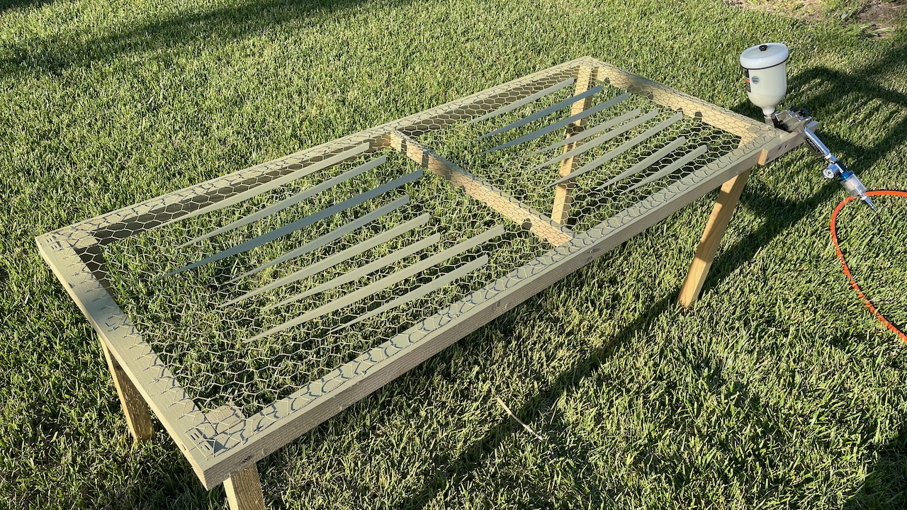
After dimpling we brought all the parts home, along with the compressor, for another round of priming using the super-awesome AZCO. I mixed up just enough primer to paint everything.
Next up is back riveting the stiffeners to the rudder skins, then moving on to the rudder “skeleton”, which includes the giant lead counterweight (think big fishing line weight), and the challenging trailing edge and curling the leading edge.